36
2021-04-12 / V1.1
Maintenance
Contactors CP Series – Installation and Maintenance Instructions
9.3.5 Replacing the auxiliary switch
assembly
Safety
DANGER
Before beginning any work on the contac-
tors, make sure that
X
there is no voltage present,
X
all safety regulations are fully ob-
served.
X
Refer also to section „Dangers and
security measures“ on page 6.
Spare parts required
- Auxiliary switch assembly 2x S826
- Auxiliary switch assembly 2x S870 a1/b0
See chapter “10. Spare parts”
Tools required
- Hexagon socket wrench set
- Circlip pliers (external)
- Torque wrench
Preliminaries
- The CP main contactor is completely dismounted
from the mounting frame or plate, see “8.2 Mechani-
cal installation”.
- The control wires at the auxiliary switches are discon-
nected, see “8.4.4 Connecting the auxiliary switches”.
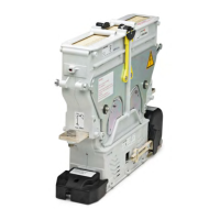
Removing the auxiliary switch assembly
Remove the auxiliary switch assembly on both sides.
On the right hand side:
X
Remove the shaft circlip (1).
X
Unscrew the 2 xing screws (2).
X
Pull the actuating arm from shaft (7) and remove
the auxiliary switch assembly (3).
On the left hand side:
X
Remove the shaft circlip (4) from the auxiliary
switch shaft.
X
Unscrew the 2 xing screws (5).
X
Pull the actuating arm from shaft (7) and remove
the auxiliary switch assembly (6).
1
2
1.5
Nm
3
4
5
6
1.5
Nm
7
Fig. 39: NO/NC contactors – replace the auxiliary switch
assembly
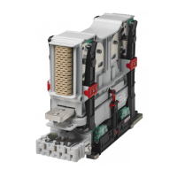
1
2
1.5
Nm
3
4
5
6
1.5
Nm
7
Fig. 40: CO contactors – replace the auxiliary switch assembly
Installing the auxiliary switch assembly
Install the auxiliary switch assembly on both sides.
On the right hand side:
X
Position the new auxiliary switch assembly (3) and
connect the actuating arm to the shaft (7).
X
Screw in the 2 xing screws (2).
X
Tighten the 2 xing screws (2) to a torque of 1.5Nm.
X
Install the shaft circlip (1) in the groove on the
shaft (7).
 Loading...