32
2021-04-12 / V1.1
Maintenance
Contactors CP Series – Installation and Maintenance Instructions
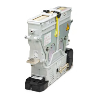
Installing the arc chamber unit
(refer to Fig. 29 and Fig. 30)
WARNING
An improperly locked arc chamber can
lead to accidents and serious personal
injury due to malfunction.
X
Make sure that the arc chamber is
securely locked.
NOTICE
An improperly locked arc chamber leads to malfunc-
tions and can destroy the contactor.
X
Make sure that the arc chamber is securely
locked.
X
Press and hold the 4 locking brackets at the top
towards the unit (1).
X
Place the complete arc chamber unit (2) on the
magnetic drive unit (4).
- Make sure that the locking brackets (1) at the
bottom engage with the locking knobs (3) on
the magnetic drive unit (4).
X
Release the locking brackets (1).
- The 4 locking brackets (1) have green markings
on the upper side. After snapping these 4 lock-
ing brackets into place (correct seating), the
green markings must be completely visible.
X
Check that the arc chamber unit (2) is securely
locked to the magnetic drive unit (4).
9.3.2 Checking the main contacts
This check is only required for devices with arc cham-
ber, but not for devices with load-free breaking capac-
ity. The cover of devices with load-free breaking capac-
ity must not be removed.
If the main contacts need to be replaced, allways re-
place all contacts (the moving bridge and the xed
contacts).
Safety
DANGER
Before beginning any work on the contac-
tors, make sure that
X
there is no voltage present,
X
all safety regulations are fully ob-
served.
X
Refer also to section „Dangers and
security measures“ on page 6.
Tools required
Suitable measuring tool to measure the minimum coat-
ing of contact material, e.g. feeler gauge, Vernier calli-
per.
Preliminaries
- The connecting cables or busbars of the main con-
tacts are disconnected, see “8.4.6 Connecting the
main contacts”.
- Only for contactor types with arc chamber: The arc
chamber unit is removed, see “9.3.1 Replacing the
complete arc chamber unit”.
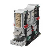
Checking the main contacts for wear and
tear
X
Check the main contacts for damage, wear and
tear, as well as traces of burn-o (slight soot de-
posits permitted).
In doing so check both,
- the contacts (1) at the xed main contacts (3)
- and the contacts (2) at the contact bridge (4).
X
If the loss of contact material is more than 70%, re-
place the xed contacts (3) and the contact bridge
(4). See
- “9.3.3 Replacing the contact bridge”
- “9.3.4 Replacing the xed contacts”
X
If the main contacts are not damaged and not
heavily worn, re-install the arc chamber unit. See
“9.3.1 Replacing the complete arc chamber unit”
2
1
1
2
3
3
4
Fig. 31: NO/NC contactors only – check the main contacts
 Loading...