18
2021-04-12 / V1.1
Installation
Contactors CP Series – Installation and Maintenance Instructions
3
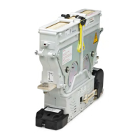
2
1
Nm
4 x M8
Fig. 13: Example for the installation of the device on a mount-
ing plate or mounting frame (the gure shows a NO/
NC device without arc chamber)
3
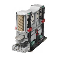
2
1
Nm
4 x M8
Fig. 14: Example for the installation of the device on a mount-
ing plate or mounting frame (the gure shows a CO
device without arc chamber)
8.3 Installation of the optional pre-
charging contactor (CPP)
The optional pre-charging contactor (CPP) can be in-
stalled:
- with 1,200 A and 2,000 A devices either at the base
plate of the main contactor or at a separate mount-
ing position next to the main contactor using the
available special mounting ange;
- with 600 A devices only at a separate mounting posi-
tion next to the main contactor using the available
special mounting ange.
A separate installation and maintenance
manual is available for CPP contactors.
Also refer to this separate manual C45-m.
Available for download at: https://www.
schaltbau.com/en/media-library/
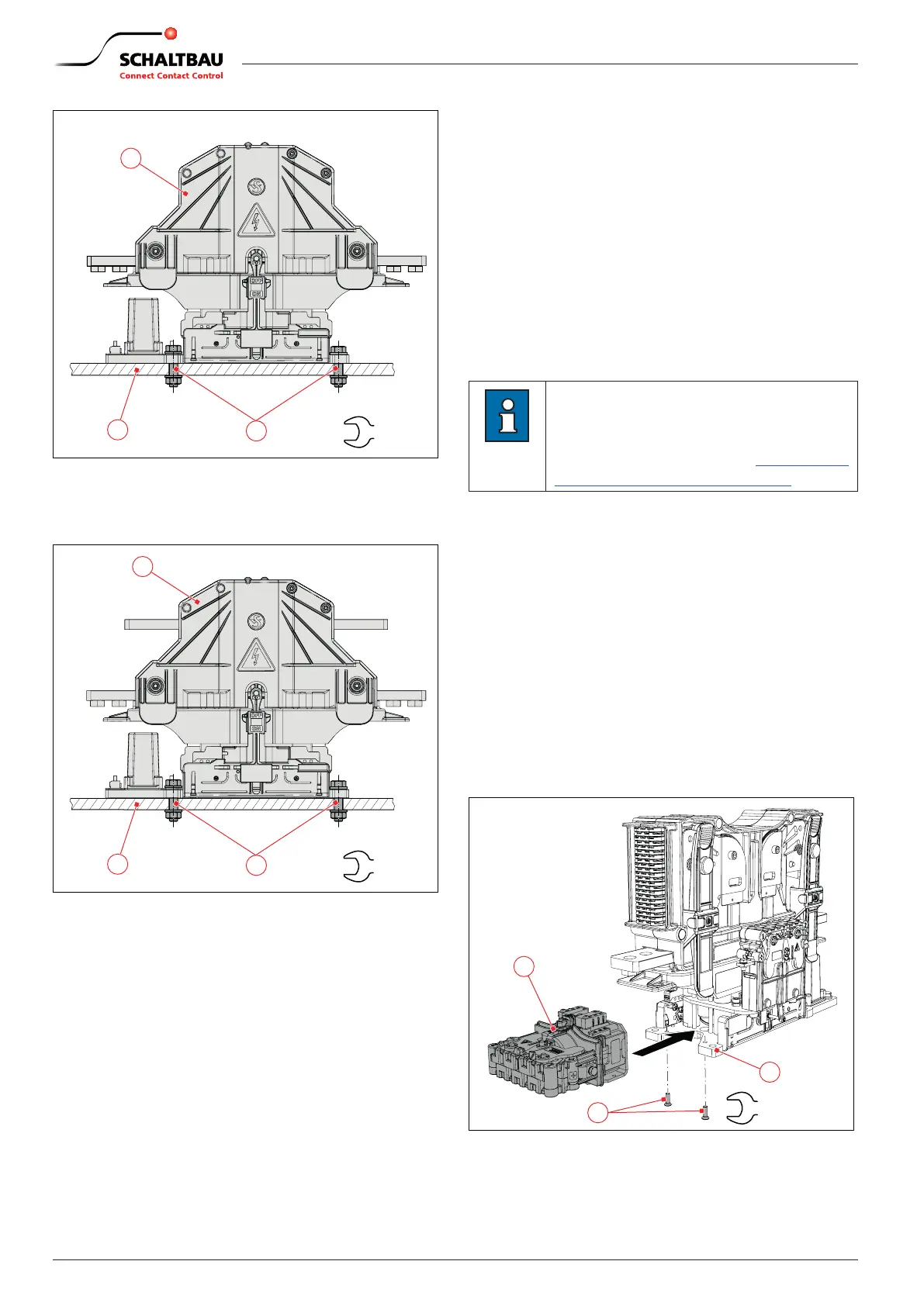
8.3.1 Installation of the CPP with 1,200A
and 2,000A devices
On delivery, the CPP is mounted at the base plate of the
main contactor as standard. The following installation
steps are only necessary in case of a subsequent cus-
tomer installation.
X
With 1,200A and 2,000A devices position the CPP
(2) at the base plate (3) of the main contactor.
X
Screw in the 2 xing screws (1).
X
Tighten the 2 xing screws (1) to a torque of 4Nm.
1
4
Nm
2
3
Fig. 15: 1,200A and 2,000A devices: Example for the installa-
tion of the CPP at the base plate of the main contactor
 Loading...