EasyManuals Logo

SCHUNK GWB Series User Manual

SCHUNK GWB Series
44 pages
To Next Page IconTo Next Page
To Previous Page IconTo Previous Page
Page #22 background imageLoading...
Page #22 background image
Assembly
22
02.00 | GWB | Assembly and Operating Manual | en | 389122
2 x Ø8.6
32g6
3
4
1
2
5
6
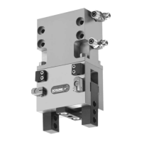
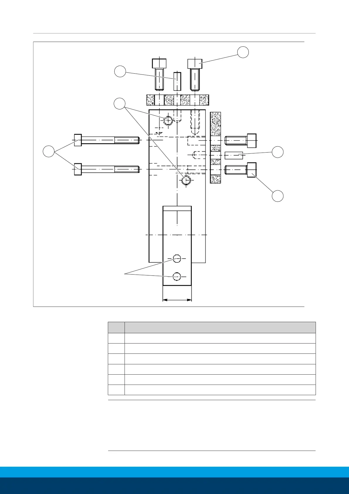
Mounting and centering the GWB 100
Item GWB100
1 4x DIN EN ISO 8734 - Ø 8m6 x 20
2 M5 for hose connection
3 4x DIN EN ISO 4762 - M8 x 65
4 4x M10 screw - 15 mm depth of engagement
5 2x DIN EN ISO 8734 - Ø 8m6 x 20
6 4x M10 screw - 15 mm depth of engagement
NOTE
When mounting the module from the rear or side, use the
fixing bores provided.
Fasten the module using the fixing bores provided.
Fasten the top jaws using the fixing bores provided.

Table of Contents

Other manuals for SCHUNK GWB Series

Questions and Answers:

Question and Answer IconNeed help?

Do you have a question about the SCHUNK GWB Series and is the answer not in the manual?

SCHUNK GWB Series Specifications

General IconGeneral
BrandSCHUNK
ModelGWB Series
CategoryIndustrial Equipment
LanguageEnglish

Related product manuals