Assembly
14.00 | JGP | Assembly and Operating Manual | en | 389157
23
Connections at
the housing
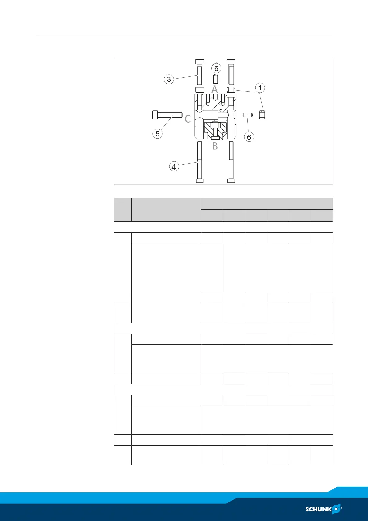
The product can be mounted from three sides.
Connections at the housing
Item Mounting
JGP
40 50 64 80 100 125
Side A
1 Mounting screw M3 M4 M5 M5 M6 M8
Max. depth of
engagement from
locating surface
[mm]
for variants IS/AS
6
9
11
16
12
18
15
18
14
16
20
20
2 Centering sleeve Ø5 Ø6 Ø8 Ø8 Ø10 Ø12
6 Fitting bore for
centering pin [mm]
– – Ø4
H7
Ø4
H7
Ø5
H7
Ø6
H7
Side B
4 Mounting screw M2.5 M3 M4 M4 M5 M6
Mounting screw
according to
standard
DIN EN ISO 4762
2 Centering sleeve Ø5 Ø6 Ø8 Ø8 Ø10 Ø12
Side C
5 Mounting screw M2.5 M3 M4 M5 M6 M8
Mounting screw
according to
standard
DIN EN ISO 4762
Max. strength class 8.8
3 Centering sleeve Ø5 Ø6 Ø8 Ø8 Ø10 Ø12
7 Fitting bore for
centering pin [mm]
– – Ø4
H7
– Ø5
H7
Ø6
H7