Assembly
28
10.00 | PGN-plus-P | Assembly- and Operating Manual | en | 389753
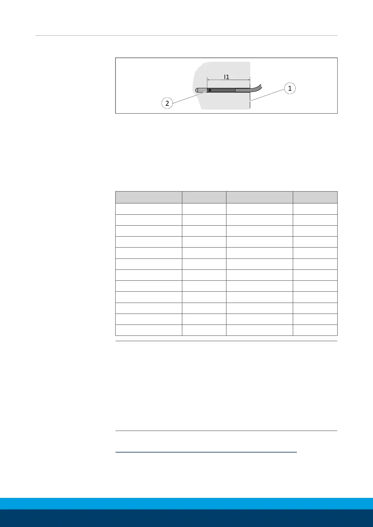
5.4.2 Setting dimensions for magnetic switches
* Setting dimension I1, from product bottom edge (1) to front sensor (2)
The setting dimension applies for the following sensors:
• Programmable magnetic switch MMS 22-PI2
• Programmable magnetic switch MMS-P 22
• Programmable magnetic switch MMS 22-PI1
• Magnetic switch MMS 22-IOL
• Analog magnetic switch MMS 22-A
Size l1* [mm] Size l1* [mm]
40 11.9 100 27
40 AS 11.9 100 AS 27
40 IS 21.9 100 IS 53
50 22 125 30
50 AS 22 125 AS 30
50 IS 38 125 IS 60
64 17.8 160 38
64 AS 17.8 160 AS 33.5
64 IS 35.8 160 IS 78.5
80 25.8 200 40.5
80 AS 25.8 200 AS 34
80 IS 43.8 200 IS 92.2
NOTE
The magnetic switch MMS 22-PI1 can be adjusted and taught in
two ways.
• "Standard mode" allows for quick installation on the T-nut
preset by SCHUNK in the groove or the defined setting
dimension "l1."
• In "Optimal Mode", the sensor identifies the optimal position in
the groove itself.
SCHUNK recommends "Optimal Mode" for setting the sensors.
Further information on the installation of the sensor,
Mounting MMS 22-PI1 programmable magnetic switch [
}
36]