Assembly
10.00 | PGN-plus-P | Assembly- and Operating Manual | en | 389753
27
5.4 Mounting the sensor
NOTE
Observe the assembly and operating manual of the sensor for
mounting and connecting.
The product is prepared for the use of sensors.
• For the exact type designations of suitable sensors, please see
catalog datasheet and Overview of sensors [
}
27].
• For technical data for the suitable sensors, see assembly and
operating manual and catalog datasheet.
– The assembly and operating manual and catalog datasheet
are included in the scope of delivery for the sensors and are
available at schunk.com.
• Information on handling sensors is available at schunk.com or
from SCHUNK contact persons.
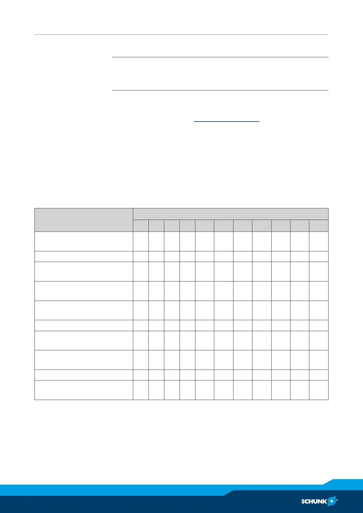
5.4.1 Overview of sensors
Designation PGN-plus-P
40 50 64 80 100 125 160 200 240 300 380
Inductive proximity switch IN
80
– – X X X X X X X X X
Magnetic switch MMS 22 X X X X X X X X X X X
Programmable magnetic
switch MMS 22-PI2
X X X X X X X X – – –
Programmable magnetic
switch MMS-P 22
X X X X X X X X – – –
Programmable magnetic
switch MMS 22-PI1
X X X X X X X X X X X
Magnetic switch MMS 22-IOL X X X X X X X – – – –
Analog magnetic switch
MMS 22-A
X X X X X X X X – – –
Analog position sensor
APS-Z80
– – X X X X X X X X X
Flexible position sensor FPS – – X X X X X X X X * X *
Analog position sensor
APS-M1
– – X X X X X X X X X
* Only for the "stroke 2" variant.