Assembly
42
10.00 | PGN-plus-P | Assembly- and Operating Manual | en | 389753
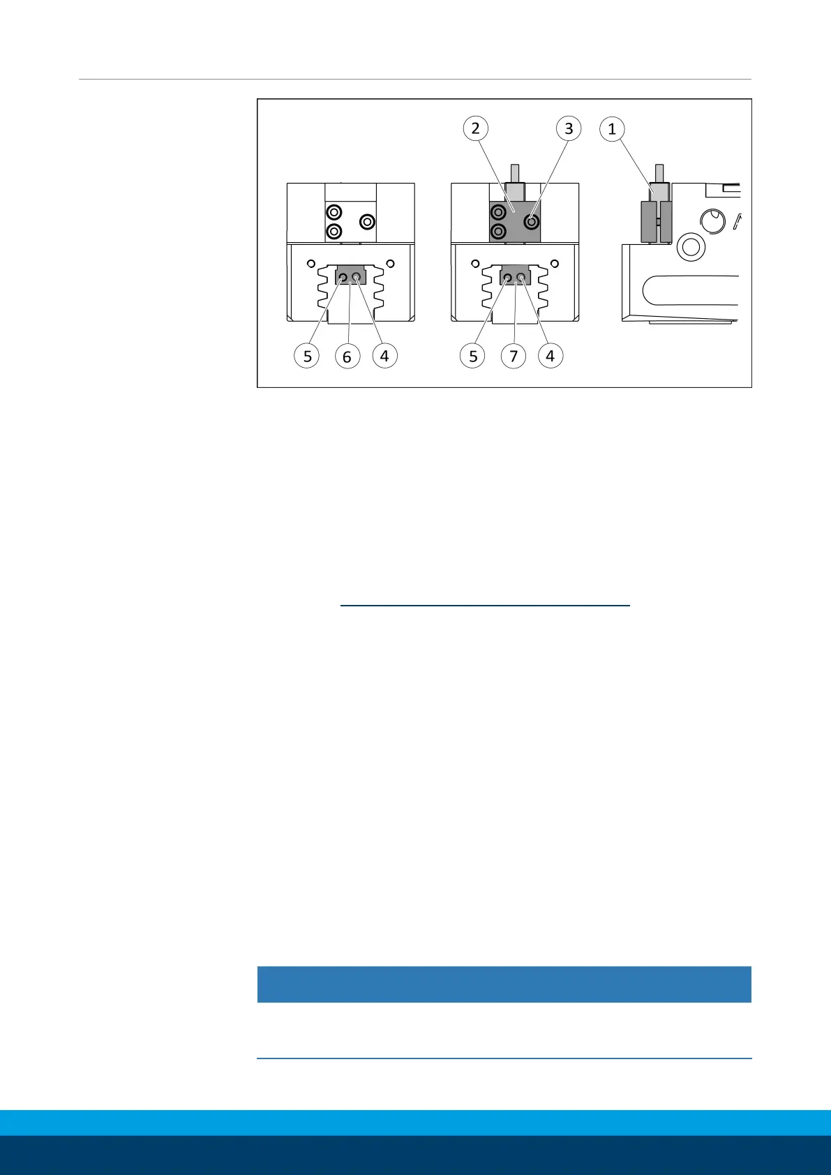
Ø Move product to the "gripper open" position.
Ø Loosen clamping spindle (4) and remove the switching cam (6)
for inductive sensing from the base jaw by turning the adjusting
spindle (5).
Ø Slide control cam (7) from the mounting kit into the base jaw.
✓ Darauf achten, dass die höhere Stirnseite der Schaltnocke(6)
nach außen zeigt.
Ø Screw the switching cam (7) into the base jaw by turning the
adjusting spindle (5) until the adjustment dimension I3 is
reached Setting dimensions for position sensors [
}
30].
Ø Fix the control cam (7) with the clamping spindle (4). It must not
be possible to move the control cam after assembly.
Ø Slide the sensor (1) to the stop into the bracket (2).
Ø Tighten the screw (3) on the bracket (2).
Tightening torque: 0.2 Nm
Ø Connect the sensor, see assembly and operating manual of the
sensor.
Variant Dust-tight:
Screw in set-screw into the side cover.
5.4.13 Mount the flexible position sensor FPS
The flexible position sensor FPS consists of an evaluation unit and
one of the following sensors:
• MMS 22-A-5V
• FPS-S M8
CAUTION
Risk of damage to the sensor during assembly!
• Observe the maximal tightening torque.