Assembly
10.00 | PGN-plus-P | Assembly- and Operating Manual | en | 389753
23
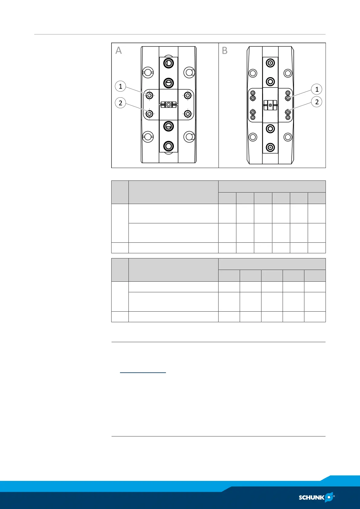
Connections for
additional structure
Connections at the housing, sizes: A - to 100, B - from 125
Item
Mounting PGN-plus-P
40 50 64 80 100 125
1 Thread in the housing M2 M2.
5
M2.
5
M2.
5
M3 M4
Max. depth of engagement
from locating surface [mm]
5 7.1 7.1 7.1 8.4 10.9
2 Centering sleeve Ø3 Ø4 Ø4 Ø4 Ø5 Ø6
Item
Mounting PGN-plus-P
160 200 240 300 380
1 Thread in the housing M5 M6 M6 M8 M10
Max. depth of engagement
from locating surface [mm]
13 12 12 12 16
2 Centering sleeve Ø8 Ø10 Ø10 Ø12 Ø14
5.2.2 Pneumatic connection
NOTE
• Observe the requirements for the compressed air supply,
Technical data [
}
17].
• In case of compressed air loss (cutting off the energy line), the
components lose their dynamic effects and do not remain in a
secure position. However, the use of a SDV-P pressure mainten-
ance valve is recommended in this case in order to maintain the
dynamic effect for some time. Product variants are also offered
with mechanical gripping force via springs, which also ensure a
minimum clamping force in the event of a pressure drop.