Protégé Portable Gas Monitor
Instruction Manual
59 of 61
P/N 087-0038 Rev. J 02/10
Figure 5-8. Pump Wiring
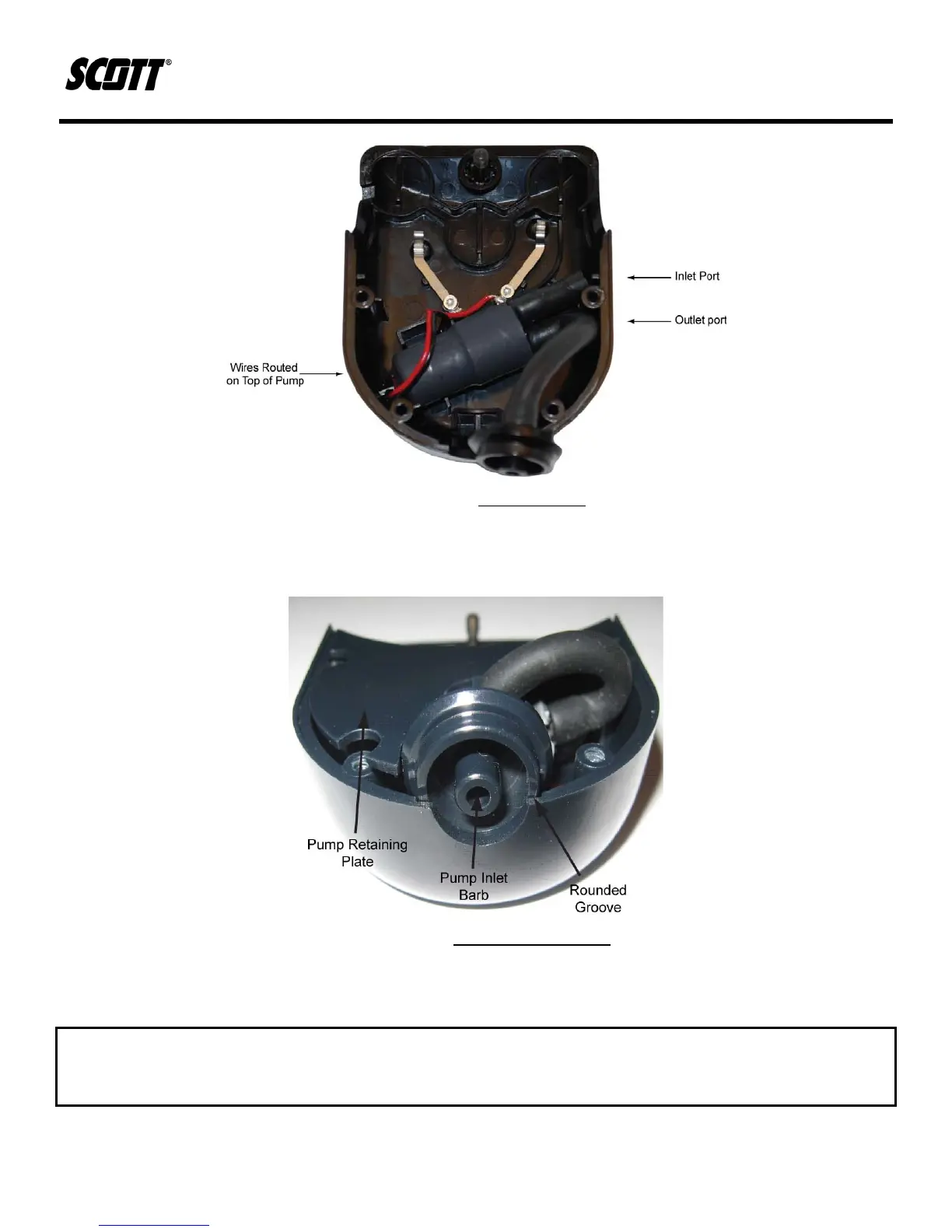
13) Insert the pump retaining plate.
14) Place the pump inlet barb into the pump enclosure groove.
Figure 5-9. Pump Reassembly
15) Gently place the back cover onto the pump enclosure and install the four (4) Torx head
screws. Follow an X pattern to ensure that the enclosure halves are seated together evenly.
CAUTION
DO NOT OVER TIGHTEN THE SCREWS. OVER TIGHTENING THE SCREWS WILL STRIP THE HOLES IN THE
ENCLOSURE.
16) Install pump onto an operational Protégé and verify proper flow rate is achieved.