- 41 -
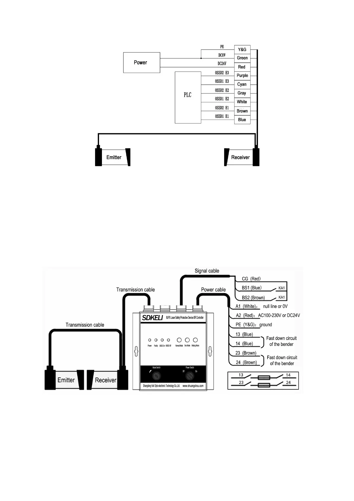
Fig.3.21 Wiring diagram of sensor
Sensor and controller used together
Wiring procedures:
1)The transmission line connects the emitter to the receiver, and the receiver to the controller.
2)Signal cable is connected to the control system of the bender.
3
)
Connect to the power supply.
4)Connect controller output according to functional requirements.
The wring diagram of SR controller is as followed:
KA1—relay controlling slow down stroke KA2—relay controlling fast down stroke
Fig.3.22 Wiring diagram of SR