- 42 -
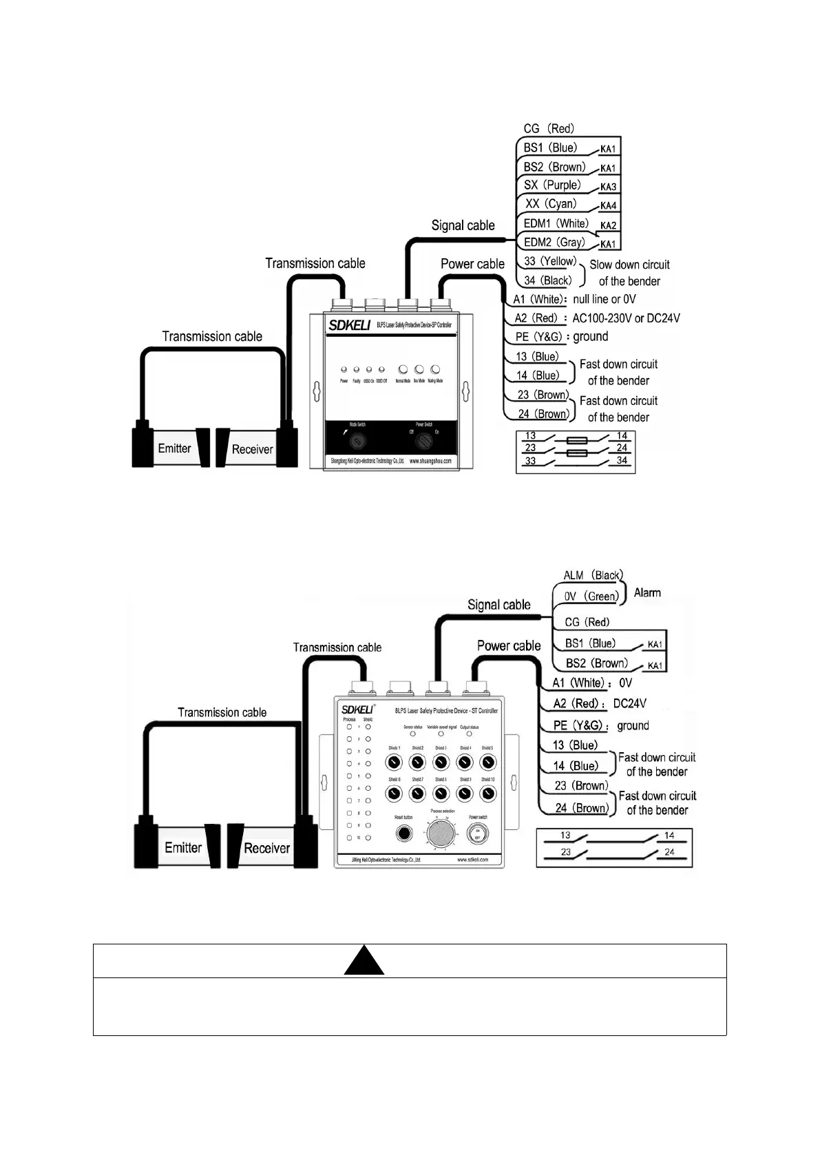
The wring diagram of SP controller is as followed:
KA1—relay controlling slow down stroke KA2—relay controlling fast down stroke KA3—relay controlling return stroke
KA4—foot switch of the bender
Fig.3.23 Wiring diagram of SP
The wring diagram of ST controller is as followed:
KA1--relay controlling slow down stroke
Fig.3.23 Wiring diagram of ST
To avoid strength created by strain and damage of connector, the end of cable close to the
connector should be relaxed properly after the wiring. The reference value of the minimum
bend radius of the cable is 7cm.