27
Control and display elements
Type 024.16.720
8. CONTROL AND DISPLAY ELEMENTS
The following chapter describes the operating statuses as well as the control and display elements of the
positioner.
Further information on the operation of the positioner can be found in the chapter entitled “13. Start-Up”.
8.1. Operating status
AUTOMATIC(AUTO)
Normal controller mode is implemented and monitored in AUTOMATIC operating status.
→ LED1ashesgreen.
MANUAL
In MANUAL operating status the valve can be opened and closed manually via the keys.
→ LED1ashesred/greenalternately.
DIP switch 4 can be used to switch between the two operating statuses AUTOMATIC and MANUAL.
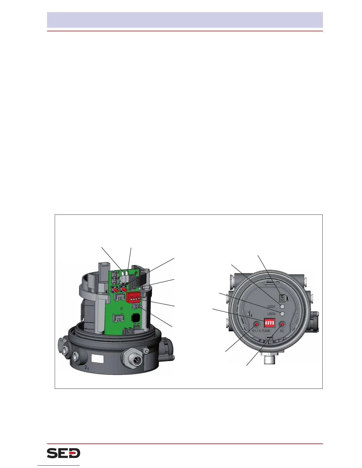
8.2. Control and display elements of the positioner
DIP Switches
Key 2
Key 1
LED 2LED 1
Communications
interface
Version 1
Version 2
1 2 3 4
ON DIP
Key 1
Key 2
LED 1
LED 2
Communications
interface
Fig. 9: Description of control elements
The positioner features 2 buttons, 4-pole DIP switches and 2x 2-colored LEDs as a display element.
→ To operate the buttons and DIP switches, for
Version 1: unscrew the body casing
Version 2: unscrew the transparent cap