41
Electrical Installation 24 V DC
Type 024.16.720
11.2. Electrical installation with circular plug-in connector
DANGER!
Risk of electric shock!
Before reaching into the device or the equipment,• switch off the power supply and secure to prevent
reactivation!
Observe applicable accident prevention and safety regulations for electrical equipment!•
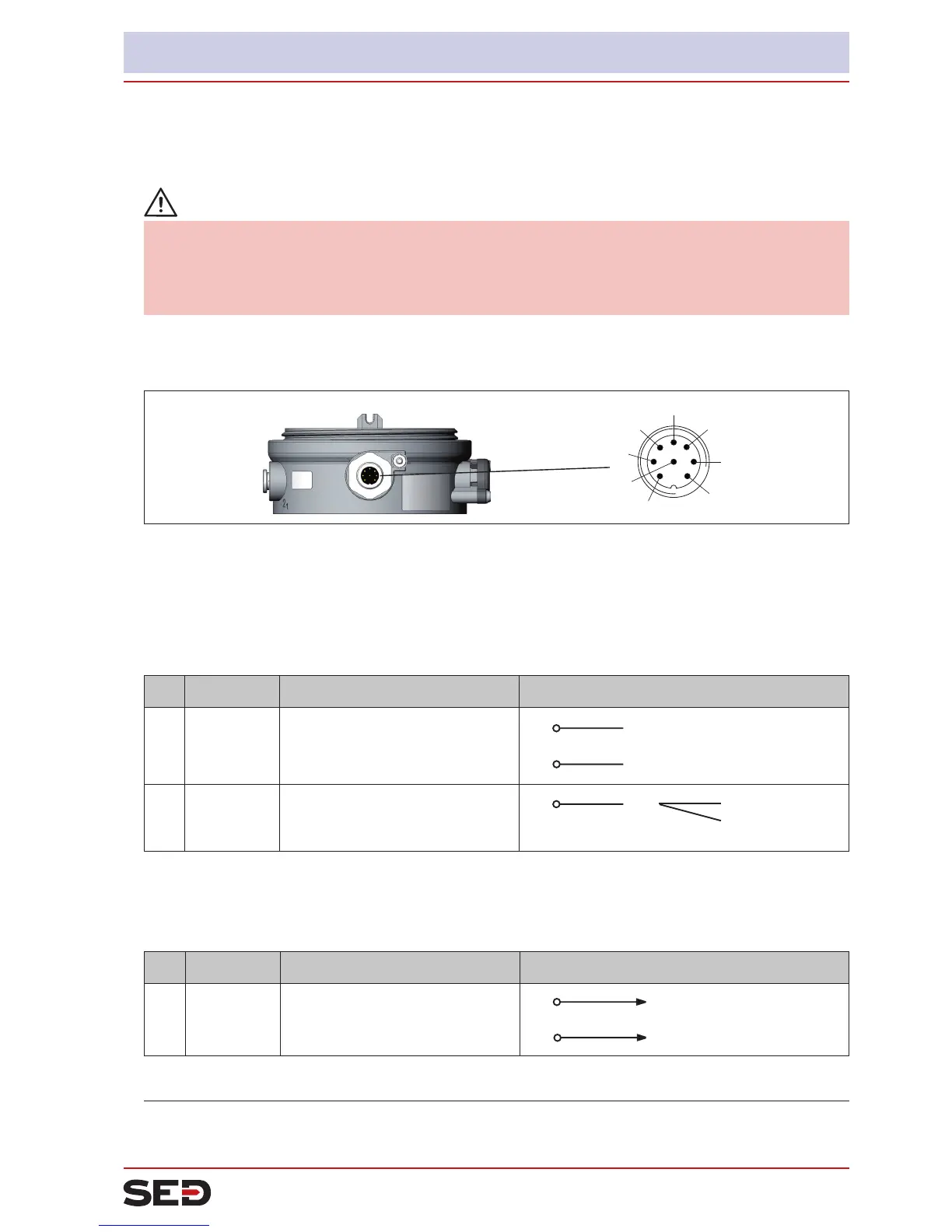
11.2.1. Designation of the contacts Type 024.16.720
View without
housing jacket
Circular plug
M12, 8-pole
6
1
7
5
4
3
2
8
Fig. 26: Circular plug M12 x 1, 8-pole
11.2.2. Connection of the positioner Type 024.16.720
→
Connect the pins according to the model (options) of the positioner.
Inputsignalsofthecontrolcenter(e.g.PLC)-circularplugM12,8-pole
Pin Wire color
1)
Conguration external circuit / signal level
1
2
white
brown
Set-pointvalue+(0/4–20mA)
Set-point value GND
1
2 GND
+ (0/4 ... 20 mA)
not galvanically isolated
5
grey Binary input +
5 +
0 ... 5 V (log. 0)
10 ... 30 V (log. 1)
with reference to Pin 3 (GND)
Table 14: Pin assignment - input signals of the control center - circular plug M12, 8-pole
Outputsignalstothecontrolcenter(e.g.PLC)-circularplugM12,8-pole
(requiredforanalogueoutputoptiononly)
Pin Wire color
1)
Conguration external circuit / signal level
8
7
red
blue
Analogue position feedback +
Analogue position feedback GND
8
7 GND
+ (0/4 ... 20 mA)
not galvanically isolated
Table 15: Pin assignment - output signals of the control center - circular plug M12, 8-pole
1)
The indicated colors refer to the connecting cable available as an accessory (919061)