SP395 SoundPro Audio Integrator Form7492 Operation Manual
101
To calibrate the microphone by entering calibration constants:
1. Select Setup & Calibration under the Utilities menu.
2. Select the “SPL” setup or calibration function.
3. Select the left or right input calibration field. Note for most measurements the left input is
used for microphone pickup and sound/acoustic measurements.
4. Enter the dBV/Pascal value into the calibration field.
5. Exit the Setup & Calibration display menu by selecting the “<” icon. The new calibration
constants values are stored into non-volatile memory upon exiting the setup menu.
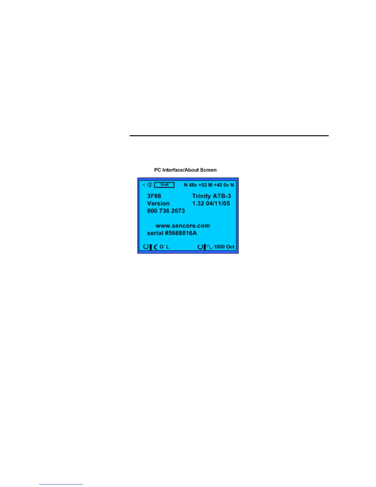
PC Interface/About
This screen provides unit information and technical support contact information about your
Audio Integrator. It shows the serial number, tech support phone number and web page address.
It displays the version number and date of the installed firmware.
The PC Interface/About screen provides unit and manufacturer information plus allows RTA, ETG graph
data to a computer
This display screen also allows you to transfer memory data, captured RTA and ETG screens, to
a computer for storage, analysis or printing. The data is in a comma delimited, ASCII format and
includes headers that identify the data.
To transfer data:
1. Connect the supplied serial adapter cable between the Serial Interface port on the
Integrator and an open serial port on the host computer. This connects the PC serial port to
the serial port on the SP395.
2. Start the application program such the SoundPro Audio Report software to transfer
memories from the Integrator to the PC program.