SP395 SoundPro Audio Integrator Form7492 Operation Manual
80
Phase Meter
The Phase Meter measures the phase difference in degrees between two input sine waves. The
sine waves must be at the same frequency but may be at different levels. The sine waves must be
stable in level and frequency for consistent measurement results.
Phase is determined by selecting a waveform as a reference. The phase difference between the
reference and 2
nd
input waveform is displayed in degrees. The phase difference is display with a
resolution of .1 degrees. You can use the Phase Meter to measure phase shift between channels
of analog equipment, such as amps, equalizers or compressors.
Phase Meter Display and Control
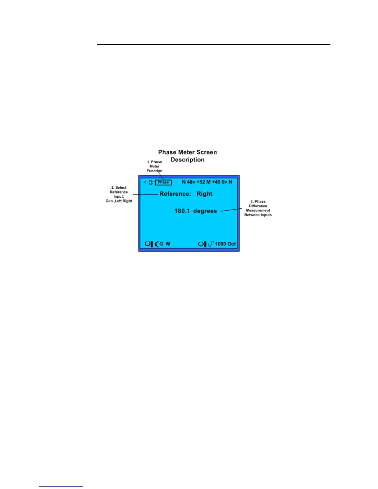
Phase Meter Test Screen and field descriptions.
1. Test Function – Identifies Phase Meter as the current test function.
2. Input Reference Select – The Phase Meter always requires two sine wave inputs. This
field selects the input or the internal generator sine wave as the reference waveform.
3. Phase Measurement Readout – Phase Difference Measurement in degrees
Phase Meter Operation
1. Turn off phantom power. Turn off phantom voltage to both inputs using the top Toolbar.
2. Connect the input. Connect two line level inputs to the left and right SP395 inputs. Note,
that if you are using the SP395 generator (Gen) as the reference, route the SP395 balanced
output back to one of the SP395 inputs.
3. Turn on the signals. If you are using the SP395 to create the test signal, turn on the sine
wave generator in the bottom Toolbar. Otherwise, create the sine wave reference and test
signals.
4. Read the results. After a short settling time, the SP395 displays the phase offset between
the 2 inputs in degrees.