SP395 SoundPro Audio Integrator Form7492 Operation Manual
22
7. Left Input Gain There are 12 selectable input gain settings. Click and turn to select the
gain for this channel. A blinking value or digits indicate clipping and the need to reduce
the gain selection number.
8. Auto-Gain. Select manual (M) or auto (A). In auto-gain, the gain setting for the channel
is automatically adjusted to prevent clipping and to have enough gain for accurate
measurements. Note that in some functions, such as Leq, you may want to hold the gain at
a fixed level. In this case, choose manual (M).
9. Right Input Gain There are 12 selectable input gain settings. Click and turn to select the
gain for this channel. A blinking value or digits indicate clipping and the need to reduce
the gain selection number.
10. Right Phantom power Click to select the icon, then turn clockwise to enable phantom
power (48v), or counter-clockwise to disable phantom power (0v).
11. Right channel polarity reverse The N/R icon changes the left input from normal (N)
polarity to reverse (R) polarity.
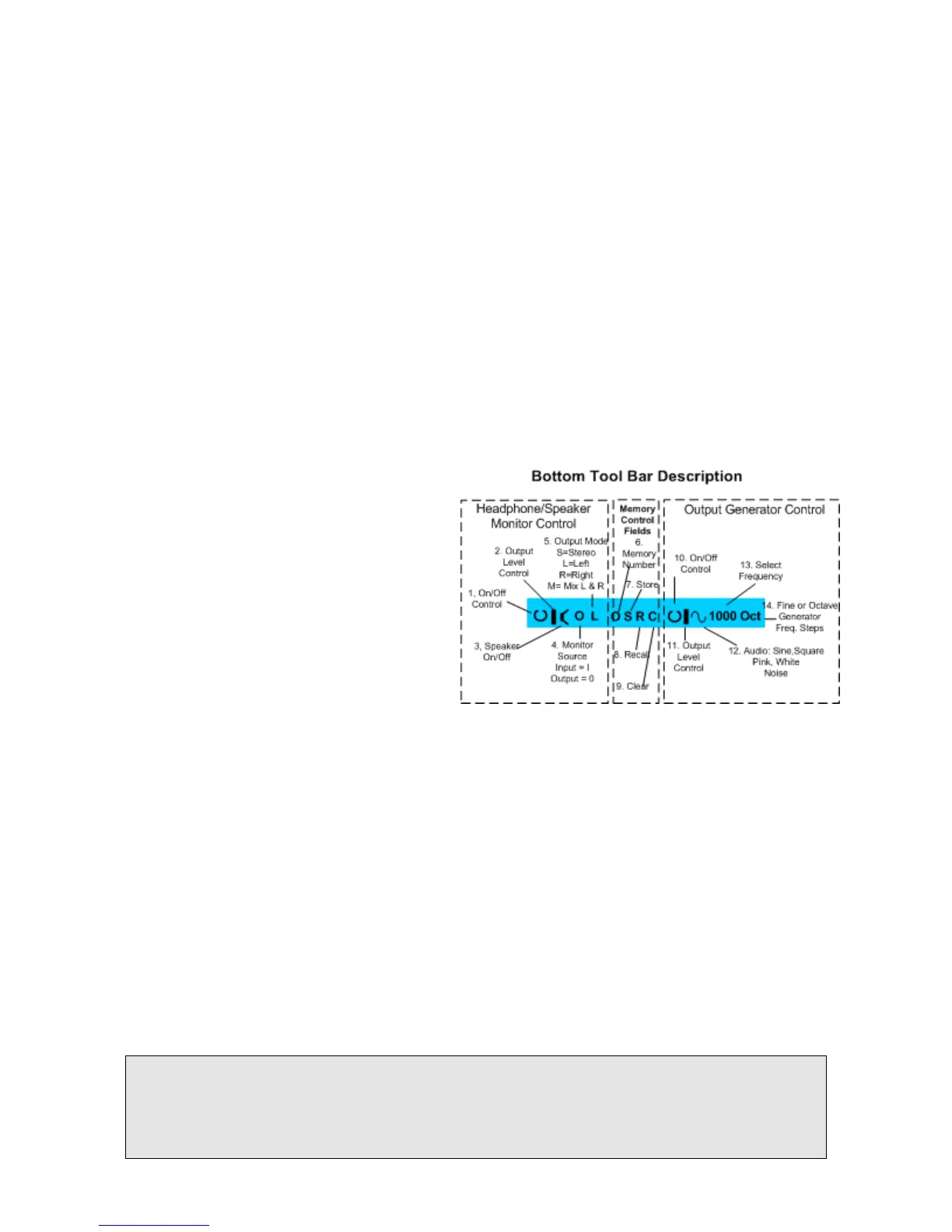
Bottom Tool Bar
The bottom toolbar contains three functional control sections. The sections include:
1. Headphone/Speaker Monitor
2. Memory
3. Output Generator
All or part of the bottom tool bar sections or
selections within each section may be
present in the various test functions of the
Audio Integrator.
The Bottom Tool Bar provides
headphone/speaker, memory, and internal
generator control.
Headphone/Speaker Monitor Control
The five icons at the left end of the bottom toolbar control the monitor output.
1. Monitor Output On/Off The 1/0 icon turns the analog monitor output on and off. This
controls both the headphone jack and the built-in speaker.
2. Level The bar level gauge icon controls the analog output level. Every turning step of the
control knob changes the output level by approximately 1 dB.
3. Speaker On/Off. This icon turns the speaker on and off. The speaker can be turned off,
even when the headphone output is enabled. To hear the speaker output, both the Monitor
On/Off and the Speaker On/Off must be turned on.
4. Source The I/O source icon determines the source for the monitor output. The I selects
the Input for monitoring, the O selects the Output signal (usually the internal digital
generator) for monitoring. Therefore, in Input mode you will hear exactly what is being
received, as selected by the input select field on the top toolbar, and in Output mode, an
exact copy of the digital output signal will be routed to the headphone jack.
5. Mode. The monitor mode field changes between stereo (S), left mono (L), right mono
(R), and the mixed left and right channels (M).
Headphone Warning: Be careful when wearing headphones and changing input connections,
input gain, and phantom power. Although the analog output is usually muted in situations that may
cause high output, unexpected loud volume may occasionally occur at the headphone output. We
recommend turning off the output before changing functions, and in other situations that may cause
loud volume.