SP395 SoundPro Audio Integrator Form7492 Operation Manual
9
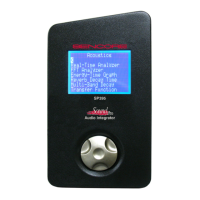
Front Panel Description
1. Display Screen: Provides a visual
interface to the user of all instrument
functions and test results.
2. Left Side Panel: Contains
Computer, USB and analog audio
jacks and speaker. See Left Side
Panel Description section for details.
3. Right Side Panel: Contains power
input jack, audio input jacks, on/off
switch and contrast control. See
Right Side Panel Description section
for details.
4. Control Knob: Provides navigation
through instrument menus. All test
operations and user selections are
performed using this control. This
control is both rotated and pressed.
Rotate the control to move the
screen cursor or increment through menu selections. Momentarily pressing inward
(clicking the control knob) makes a selection or change.
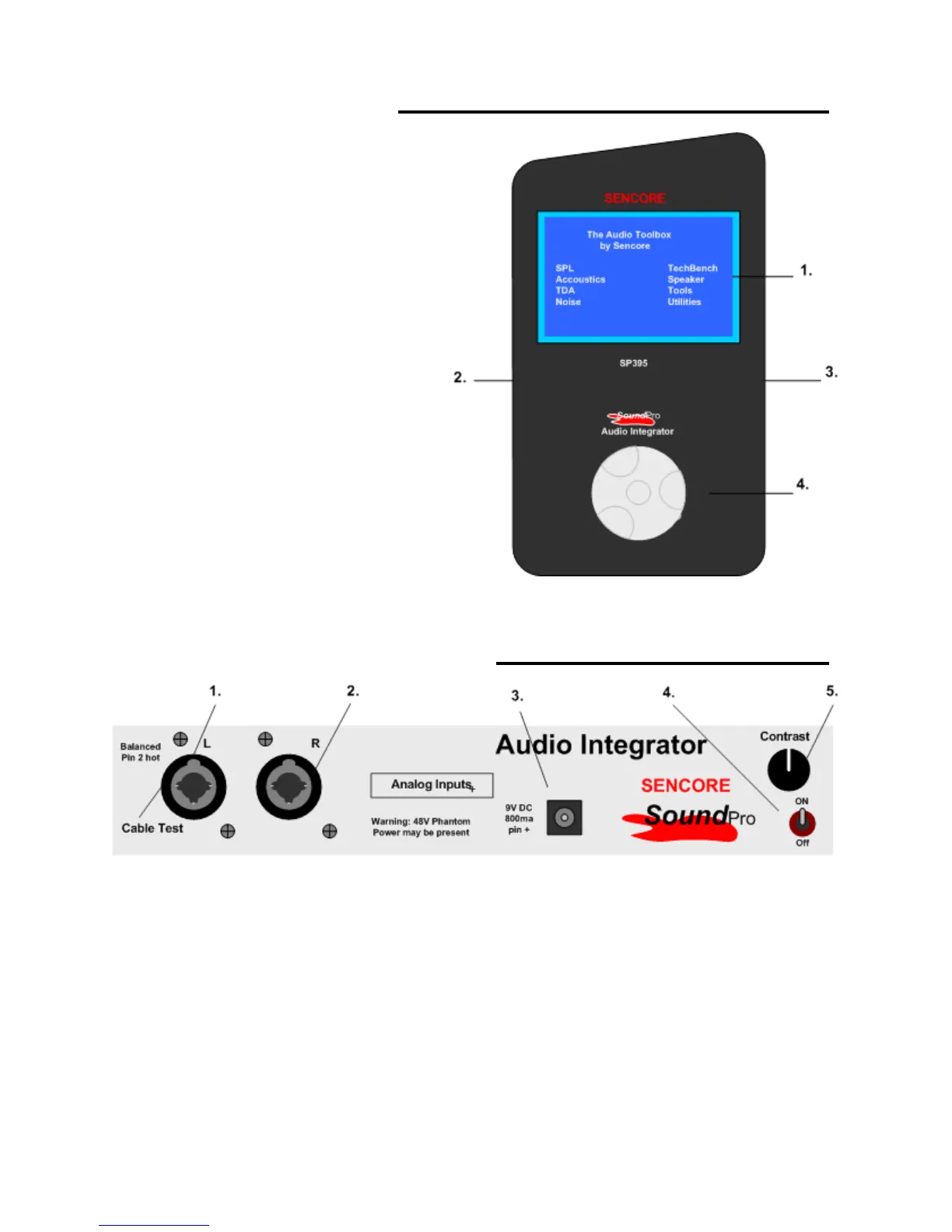
Right Side Panel – Input Description
1. Left Analog Input: Combination XLR and ¼ inch Balanced Microphone /Line input.
Used as main input for most tests. May have 48 Volt Phantom Power switched to jack by
instrument. Used as Cable Test Input.
2. Right Analog Input: Combination XLR and ¼ inch Balanced Microphone /Line input.
May have 48 Volt Phantom Power switched to jack by instrument.
3. Power Adapter Input: Powers the instrument and charges the internal rechargeable
battery. Use a Sencore approved adapter nominal 9V @ min 800 mA. (Center pin
positive)
4. Power Switch: Turns the instrument power on or off. Down is Off.
5. Contrast Control: Sets the contrast of the display screen for best viewing.