SP395 SoundPro Audio Integrator Form7492 Operation Manual
71
Level/Freq. Meter
The Level Meter measures and displays the Left and Right audio input levels simultaneously.
You can use either XLR connectors or 1/4 inch connectors to the either or both of the audio
inputs. The level meter measures input signals over a wide range from -120 dBu to +40 dBu.
The resolution varies with the input range providing resolution to .001 uV.
Levels are metered using various display units including V rms, Vp-p, dBu, dBV or dBr.
dBu is based upon 0 dBu being equivalent to .775 V rms.
dBm is based upon 0dBm being 600 mW of power.
0dBV is based upon 0 V as the reference level.
All measurements are performed in averaging mode, which is the same method used by the
meters on most tape recorders, consoles, and outboard equipment, so the SoundPro readings
conform to the readings of most recording studio signal level meters.
The Level/Freq. meter contains a frequency counter to measure the frequency of the incoming
audio sine-wave signals. The frequency counter measures and displays the frequency of both the
right and left audio channel input simultaneously. The frequency counter range is from 10 Hz to
32 kHz.
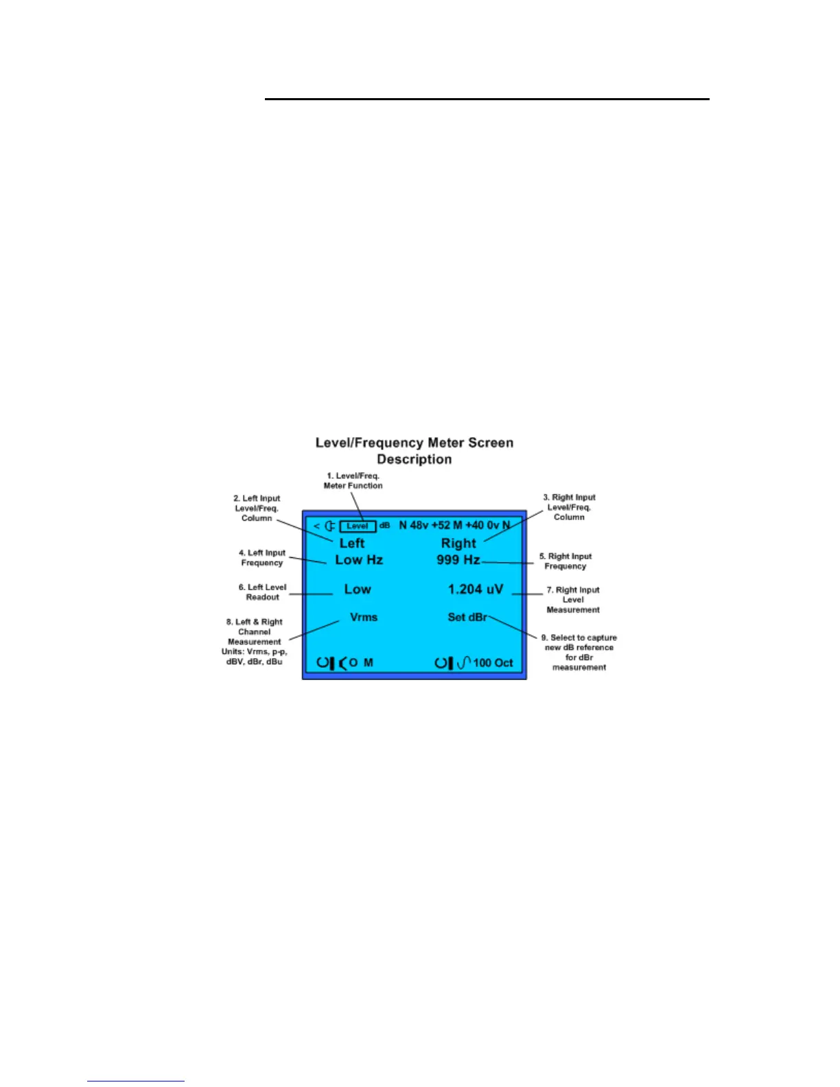
Level/Frequency Meter test screen and field descriptions.
Level/Freq. Meter Display Screen
1. Test Function – Identifies Stethoscope (Steth) as the selected function and measurement
screen.
2. Measurement Filter – Selects measurement filter applied to input from left channel.
Includes selection of A weighted, C weighted, octave or sub-octave filters.
3. Headphone On/Off – Turns on or off audio from the left input to the headphone jack.
4. Left Input Frequency – Indicates the frequency of the left audio input sine-wave.
5. Right Input Frequency – Indicates the frequency of the right audio input sine-wave.
6. Left Channel Input Level – Indicates the left audio input level measurement value.
7. Right Channel Input Level – Indicates the right audio input level measurement value.
8. Measurement Units – Selects the unit of measurement for the level readout on both the
left and right meter.
9. dBr Reference Level Capture – Select and click to capture a reference level for both the
left and right channel for dBr measurements. Select dBr as the measurement unit to meter
how the left and right audio input levels are changing compared to the captured reference
level.