SP395 SoundPro Audio Integrator Form7492 Operation Manual
86
Impedance Meter
The Impedance Meter measures the AC opposition or “impedance” offered by a passive device,
such as an audio speaker, to an audio frequency. It may also be used to measure the input
impedance of audio devices at a specific frequency. It computes the power that would be
required to drive a constant voltage speaker network, at a particular voltage. The output level and
waveform are fixed in this function.
Impedance Meter Display and Control
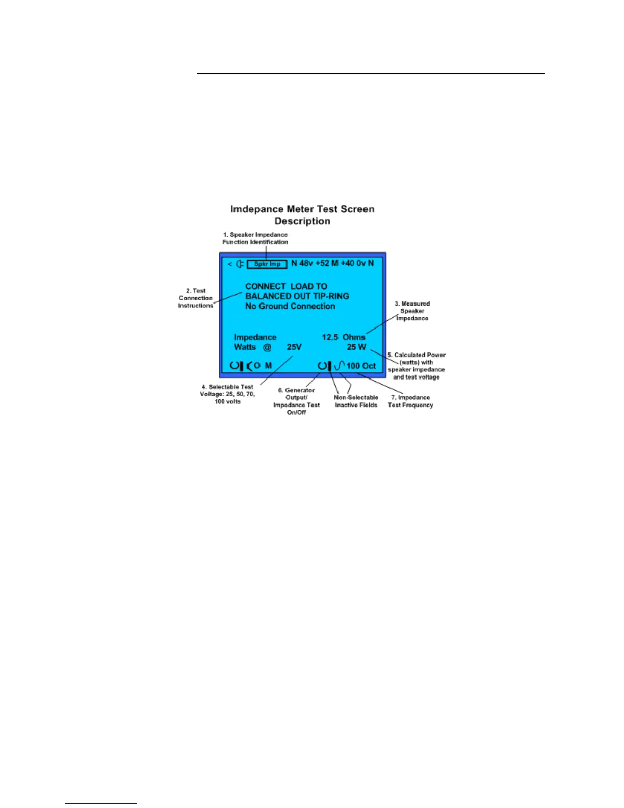
Impedance Meter Display and description of control fields.
1. Test Function – Identifies Impedance Meter as the active test function.
2. Test Connection Instructions – Instruction on how to connect the balanced output to a
load for measurement. Use the specialty Impedance Test Cable, Sencore #39G1171. This
cable provides the proper connection from the ¼ inch mono (balanced) plug to clip
connections which can be connected to a device or input to be tested.
3. Test Impedance - Measured impedance value determined by the Impedance Meter.
4. System Voltage Selection – Selects the distributed audio system voltage used by the
Impedance Meter to calculate load power (watts). Use to calculate load power of an audio
distribution system based upon the measured impedance and one voltage level.
5. Calculated Power watts – Computed from selected voltage and measured impedance
values. Shows power (watts) required by the system to drive the system to full output
power.
6. Generator – Impedance Test On/Off – Turns the Impedance Meter function on or off.
7. Generator/Test Frequency – Test frequency of the Impedance Meter.
Note: The Generator level and waveform selection fields are not selectable or variable in the
Impedance Meter function.