SP395 SoundPro Audio Integrator Form7492 Operation Manual
85
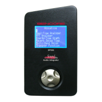
4. Distortion Meter Test Readout – Indicates distortion test results in dB.
5. Test Function Identification – Test Indicator only – this field is not selectable.
6. Distortion Meter Readout – Digital value indicating % of speaker distortion.
7. Measurement Scale – Fixed scale used to graphically indicate distortion %. Not
selectable or variable.
8. Distortion Meter Indicator – Arrow indicator that marks a distortion level on the visual
scale indicating % distortion. This graph displays the speaker distortion percentage
displayed on an analog bar graph, ranging from 100% (left) to 0.0001% (right).
9. Generator On/Off – Turns generator output on or off.
10. Generator Output Level – Indicates and provides level adjustment for the generator
output.
11. Generator Waveform – Selects generator output waveform. The waveform type should
be a sine-wave for the THD + N test.
12. Generator Test Frequency –Indicates the frequency output of the generator. The
frequency should match the frequency of the THD+N test selection.
Speaker Distortion Test Operation
1. Connect the SP395’s Output to the amplifier input. The SP395 must be the signal
source for the distortion test. Connect the output to the amplifier that is driving the
speaker to be tested. Set the amplifier gain at 1/3 to 1/2 volume. (You will not hear an
output from the speaker until the test is turned on).
2. Select the desired Test Frequency. Test full-range speakers at each frequency; sub-
woofers at 63 and 125 Hz; satellite, bookshelf and PA speakers at 125 Hz and above.
3. Set up the Input. Turn off the phantom power, set the input gain (auto-gain may be used),
and connect the device output to the SP395’s left input.
4. Set the Output Level to minimum. The speaker volume depends on the SP395 Output
Level and the amplifier volume. Caution: Start with the output level at minimum to
prevent speaker damage when the distortion test is turned on.
5. Turn on the Speaker Distortion Test. Click generator on/off field in the bottom Toolbar.
(A line appears in the headphone symbol indicating the audio output is on)
6. Increase the Output Level. Increase the audio output level using the bottom Toolbar until a
clear test tone is heard from the speaker.
Caution: If you do not begin to hear an output
from the speaker as you increase the output level, check the connections between the
SP395 and amplifier, the amplifier input and speaker selection switches, and the amplifier
volume setting.
7. Read the speaker distortion. The percent of speaker distortion is shown on the digital
display and on the analog bar graph.
8. Test the speaker at all appropriate test frequencies.
9. Full-range speakers at each test frequency.
• Sub-woofers at 63 and 125 Hz.
• Satellite, bookshelf, and PA speakers at 125 Hz and above.
• Caution: Reduce the Output Level before changing the test frequency.
10. Test the remaining speakers in the audio system.
Caution: Reduce the SP395 Output Level before switching speakers or amplifier inputs.