SP395 SoundPro Audio Integrator Form7492 Operation Manual
34
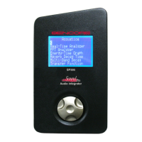
Storing an RTA graph to memory:
Real-Time Analyzer graphs can be stored in any of the 40 non-volatile memories, using the
memory control icons in the center of the bottom toolbar. Use the memory number field to
select a memory number. See the Bottom Toolbar section of this manual for details on the
memory toolbar section. When the memory number field is selected, the type of memory
stored (or “---” if empty) appears on the bottom of the graph. The memory type for the Real
Time Analyzer is labeled “RTA”.
To store an RTA to memory:
1. Select a memory number in the memory number field. Note: The display indicates if a
previous test screen is stored or “- -” if empty.
2. Store to memory - Click on the S (Store) icon to store the function data to the current
memory number.
3. Recall from memory - Click on the R (Recall) icon to recall function data from a selected
memory number. If the data type does not match the current function, a “Wrong type”
error message will appear momentarily. A recalled graph can be analyzed exactly the
same as a live graph - by changing the octave band filter size, graph amplitude range, and
using the cursor to read individual band frequencies and dB levels. Memory data can also
be transferred to a PC using the Transmit Data function.
4. To Clear memory. Click on the C (Clear) icon to clear function data from the current
memory number.
RTA - Difference Mode
You can operate the RTA in a difference (Diff) mode. This allows you to see how current
conditions differ from a stored memory RTA. It is especially useful to compare seating position
RTAs or to judge how changes to the room affected the acoustic performance.
To use the RTA difference mode, you must first either recall or save a memory. Then, change the
overlay field to ‘Diff’ and the display will switch to difference mode. The center of the screen
will be set to 0 dB, with a ±15 or ±7.5 dB scale, depending on the graph resolution selected (top
left corner of RTA graph). To exit difference mode, change the ‘Diff’ in the overlay field to
“Flat.”
Real-time Interface
The RTA function can be used with the TerraLink computer software program to provide read
time measurements on a PC screen. See the TerraLink Control – Real Time Computer Interface
section of this manual for more information.