SP395 SoundPro Audio Integrator Form7492 Operation Manual
78
IMD Description
Inter-Modulation Distortion (IMD) is another distortion measurement used in audio equipment
testing. IMD is measured by applying a two-tone test signal to the device under test and
measuring the distortion components resulting from this test signal. The SP395 supports both
SMPTE IMD testing, using a 7 kHz/60 Hz composite waveform, and DIN IMD testing, using an
8 kHz/250 Hz composite waveform. This function is used very much like the THD+N function.
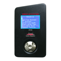
IMD Test Screen and descriptions of control fields.
Distortion Meter Control Field Descriptions:
1. Test Function – Identifies Distortion Meter as the menu selection.
2. Distortion Type – Selects the type of distortion test either IMD or THD
3. Test Frequency or Standard – Selects the frequency of the THD+N distortion test.
Note:
the generator low distortion sine-wave test frequency must agree with this frequency.
Selects the SMPTE IMD test (7kHz/60Hz) or DIN IMD test (8kHz/250Hz).
4. Input Select – Selects either the right or left input for the distortion test.
5. Distortion Meter Test Readout – Indicates distortion test results in dB.
6. Test Function Identification – Test Indicator only – this field is not selectable.
7. Distortion Meter Readout – Digital value indicating % of distortion for test.
8. Measurement Scale – Fixed scale used to graphically indicate distortion %. Not
selectable or variable.
9. Distortion Meter Indicator – Arrow indicator that marks a distortion level on the visual
scale indicating % distortion.
10. Generator On/Off – Turns generator output on or off. Active for all distortion tests.
11. Generator Output Level – Indicates and provides level adjustment for the generator
output. Active for all distortion tests.
12. Generator Waveform – Selects generator output waveform. The waveform type should
be a sine-wave for the THD + N test. This field does not appear in the IMD test as a
special two tone test signal is generated and output by the generator.
13. Generator Test Frequency – Only shows on TDH+N test. Indicates the frequency output
of the generator. The frequency should match the frequency of the THD+N test selection.