3 Maintenance/Safety & Functionality Tests
HB-005615-j
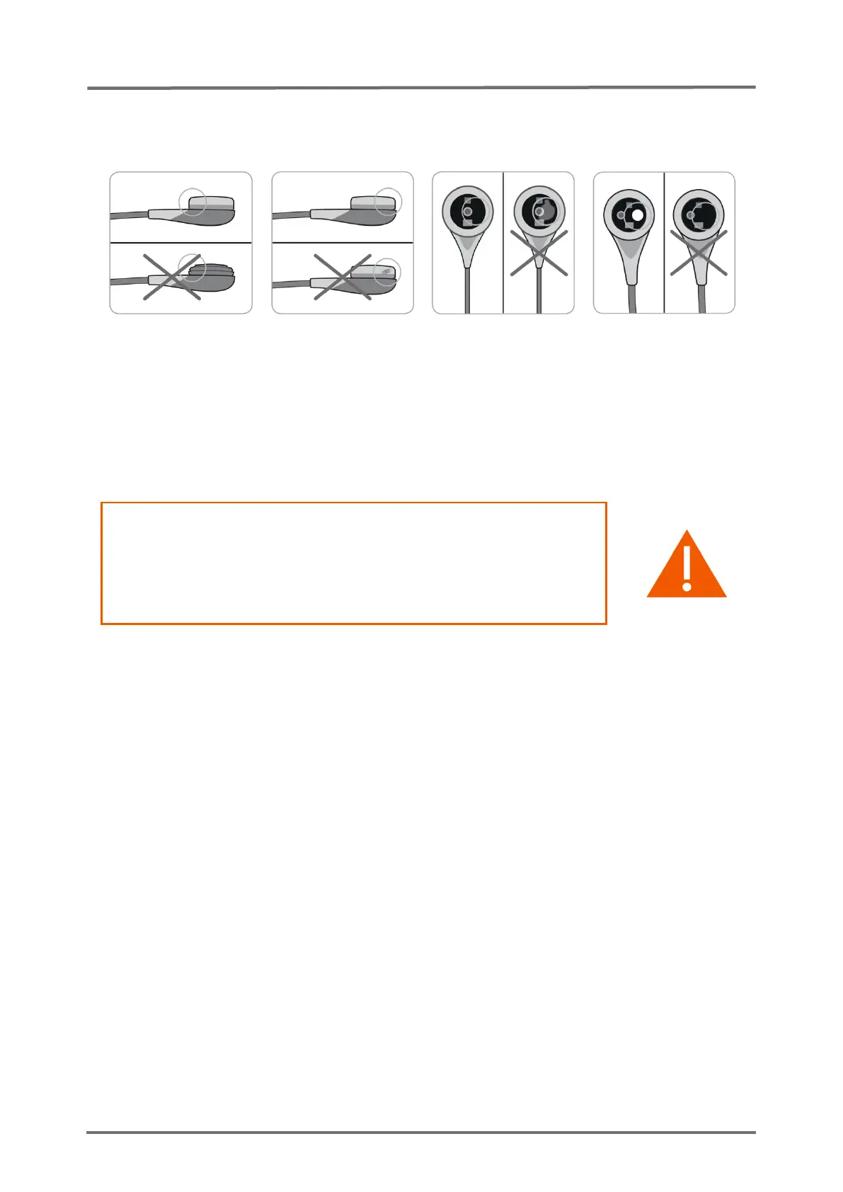
In case of loose fit, damage or trapped air you must repeat the
membrane change. Otherwise confirm the membrane change in the menu of
the monitor and calibrate sensor.
Figure 5 Inspection after remembraning the sensor
3.1.8 PCO2 / PO2 Sensitivity & Calibration Duration
WARNING: A wrong barometer reading or a gas leak can lead
to a false positive/negative test result. Prior to performing a
‘Sensitivity Test’ verify Docking Station integrity/cleanliness (
see
section 3.3 “Docking Station”
) and barometer function (
see
section 3.2.11 “Barometric Pressure”
).
If the procedure below is not strictly followed the ‘Sensitivity Test’ will abort.
Strictly observe the indicated times. ‘Sensor problem 12’ (PCO2 sensitivity)
or ‘Sensor problem 72’ (PO2 sensitivity) will only reset, if the test was
successful.
If a V-Sign™ Sensor is connected to the SDM the function ‘Sensitivity Test’
will test the sensor`s PCO2 sensitivity. If an OxiVenT™ Sensor is connected
to the SDM the function ‘Sensitivity Test’ will test the sensor`s PCO2 and
PO2 sensitivity in parallel.
Test the PCO2/PO2 sensitivity as follows:
1. Verify that the sensor SET temperature is 42°C (in case of a V-Sign™ Sensor) or
43°C (in case of an OxiVenT™ Sensor) and that the local atmospheric pressure
is at least 600 mmHg (80 kPa) (see respective icon).
You may optionally activate the display of the calibration curve by
using “V-STATS™” (PC-Software for the SDM).
2. Insert the sensor into the Docking Station.
3. Use the menu-function ‘Measurement Settings / PCO2 Settings / Sensitivity Test’
OR the menu-function ‘Measurement Settings / PO2 Settings / Sensitivity Test’ to
activate the test (both menu-functions will initiate the same test). The Status