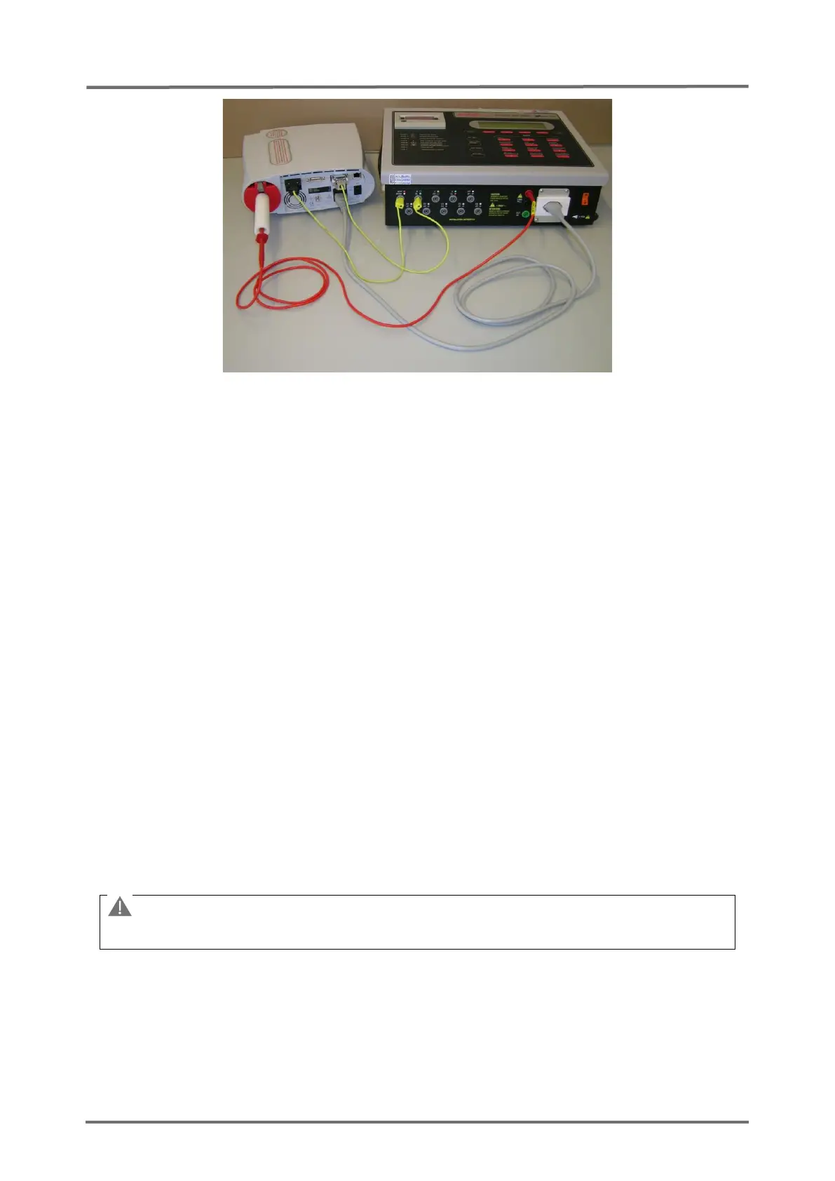
Figure 9 Connections for the Safety Test
Setup with 601PRO
XL
International Safety Analyzer from BIO-TEK
3.2.5 POST
After turning on the SDM performs a power-on self-test (POST), which tests the SDM’s
circuitry and functions (internal test). The display, as well as the visual and audible
indicators (i.e. LED’s and speaker) are activated. The result of the POST is indicated
by a (passed) or (failed) symbol. If no problems are detected during the POST the
message ‘passed’ () is displayed; else the message ‘failed’ () is displayed.
Note: The message "FLASH Memory Inside" is displayed on the POST screen, if the
hardware version of your monitor supports a non-volatile FLASH memory.
Note: The message "LAN Interface supported" is displayed on the POST screen, if the
hardware version of the SDM supports the LAN interface.
Note: The message “LED Backlight” is displayed on the POST screen, if the backlight
is a LED type.
If the POST fails, an error message shows up at the bottom of the POST screen, refer
to P0405
(see section 4.2.4 "SDM specific troubleshooting”).
The SDM needs to be
repaired according to
section 5 "Repairs".