SECTlON
2
THEORY
OF
OPERATION
2-0
INTRODUCTION
This
section
explains the
Pro-One's
hardware
theory
of
operation. The microcomputer
program (software)
is
not generally discussed
because
it
is
proprietary
and
because
the
program details
are
usually
not-relevant
to
service
problems. That
is,
you
canlt
"fixt'
the software
(you
-
can replace it,
by
replacing
the
Microcomputer
IC).
Note that
if
you
first understand the hardware
surrounding
the
microcomputer, you will
be
able
to
deduce
the basic program
functions.
2-1
GENERAL
1
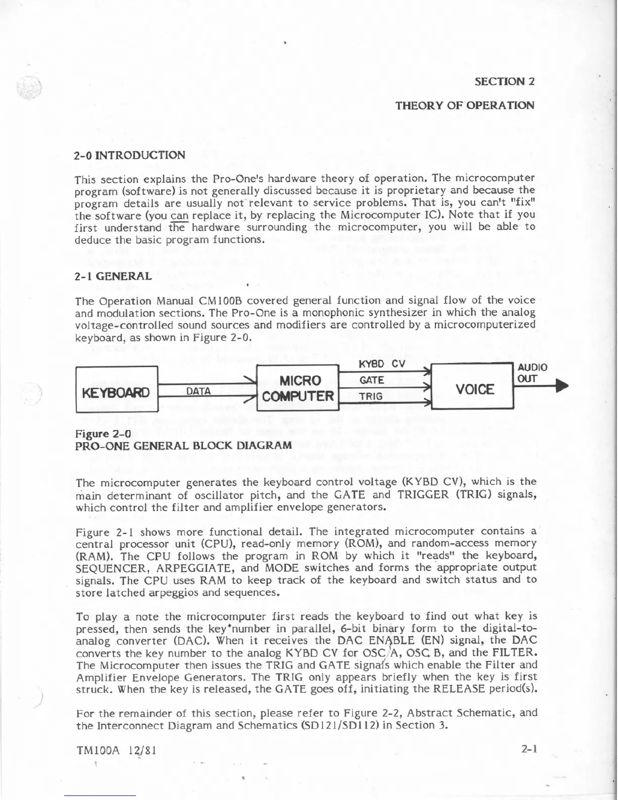
The
Operation
Manual
CMlOOB
covered
general function
and
signal
flow
of
the
voice
and modulation sections.
The
Pro-One
is
a
monophonic synthesizer
in
which
the analog
voltage-controlled
sound
sources
and
modifiers
are
controlled
by
a
microcomputerized
keyboard, as
shown
in
Figure
2-0.
Figure
2-0
PRO-ONE
GENERAL
BLOCK
DIAGRAM
r
-
KYUU
LV
AUOlQ
The microcomputer generates
the
keyboard
control voltage
(KYBD
CV),
which
is
the
main
determinant
of
oscillator pitch, and the
GATE
and
TRIGGER
(TRIG)
signals,
which
controi the
filter
and
amplifier
envelope generators.
KEYW&D
Figure
2-1
shows
more
functional
detail.
The
integrated microcomputer contains
a
central
processor unit
CCPU),
read-only
memory
(ROM3,
and random-access
memory
(RAM).
The
CPeJ
foliows the program
in
ROM
by
which
it
f'reads"
the keyboard,
SEQUENCER,
ARPEGGIATE,
and
MODE
switches
and
forms the appropriate
output
signals, The
CPU
uses
RAM
to
keep
track
of
the
keyboard
and
switch
status
and to
store
latched
arpeggios
and
sequences.
To
play
a
note
the
microcomputer first
reads
the keyboard
ta
find
out
what
key
is
pressed, then
sends
the key'number
in
parallel, 6-bit binary
form
to
the digital-to-
analog converter
(DAC).
When
it
receives the
DAC
ENbBLE
(EN)
signal,
the
DAC
converts
the
key
number
to
the
analog
KYBD
CV
for
OSC
I'A,
OSC,
8,
and
the
FILTER.
The Microcomputer
then
issues
the-
TRIG
and
GATE
signah
which
enable
the Filter and
Amplifier Envelope Generators.
The
TRIG
only
appears briefly when the
key
is first
struck.
When
the
key
Is
released,
the
GATE
goes
off,
initiating the
RELEASE
period(s1.
h.
,
DATA
9
For
the
remainder of this section, please
refer
to Figure
2-2,
Abstract Schematic,
and
the
Interconnect Diagram
and
Schematics
{SD
121JSD
112)
in
Section
3.
MICRO
GATE
COMWTER
TRIG