CEM
3310
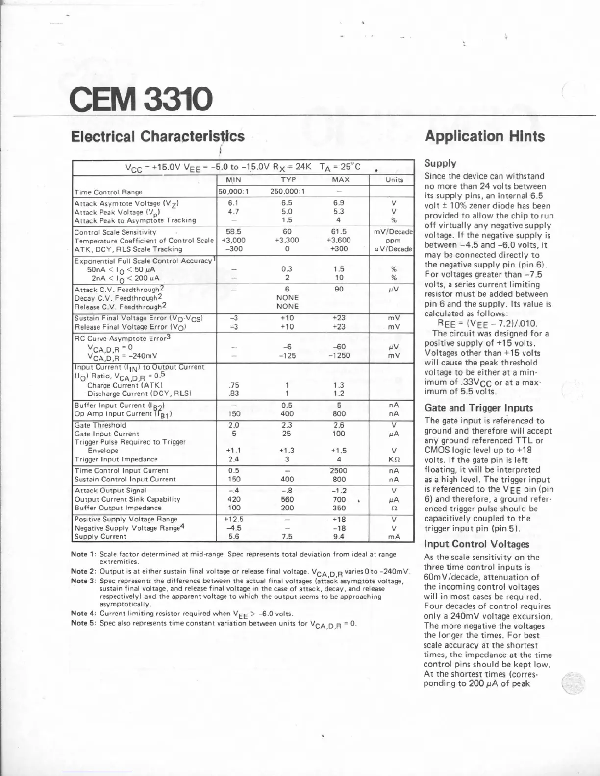
Electrical
Characteristtcs
\
equired
to
Trigger
Note
1
:
Scale
factor
determ~ned
at
mid-range.
Spec
represents total dewation
from
deal
at
range
extremrtles
Nete
2:
Output
IS
at
either
sustain
frnal
voltage
or
release final voltage.
VCA
D
R
vanes
0
to
-24OmV
Note
3:
Spec
represents
the
d~fference between
the
actual f~nal
voltages
(attic6
asymptote
voltage,
sustain final voltage, and release hnal voltage
In
the
case
of
attack. decay. and
release
recpeettvely)
end
the
apparent voltage to whrch
the
output
seems to be approach~ng
asvmprotlcally.
Note4:
Current
limiting resistor requ~red when
VEE
>
4
0
volts.
Note
5:
Spec
also
represents time constant variat~on betwen unrts
for
VCA,D,R
=
0.
Application
Hints
Since the device
can
withstand
no
more
than
24
volzs between
its supply
pins,
an internal
6.5
volt 5
10%
zener
diode
has
been
provided
to
allow
the
chip
torun
off
virtually
any
negative supply
voltage.
IF
the negative supply
is
between
-4.5
and
-6.0
volts, it
may be connected directly
to
the
negative supply pin
(pin
6).
For voltages greater than
-7.5
volts,
a
series
current
limiting
resistor must
be
added between
pin
8
and
the
supply. Its value is
calculated
as
follows:
RE€
=
(VEE
-
7.211.070.
The
circuit
was
designed
for
a
positive
supply
of
+15
volts.
Voltages other
than
+I5
volts
will cause the
peak
threshold
voltage to
be
either at
a
mfn-
imum
of
.33V~c
or
at
a
max-
imum
of
5.5 volts.
Gate
and
Trigger
Inputs
The
gate input is
refe'renced
to
ground
and
therefore will
accept
any
ground referenced
TTL
or
CMOS
logic
level
up
to
+I8
volts. If the gate pin is left
floating,
it
will
be interpreted
as
a
high
level.
The
trigger input
is referenced
to
the
V
E
E
pin
(pin
6)
and
therefore,
a
ground refer-
enced
trigger pulse should
be
capacitively
coupled
to
the
trigger input pin
(pin
5).
Input
Control
Voltages
As
the
scale sensitivity on the
three
time control inputs is
BOmVldecade,
attenuation
of
the incoming control voltages
will
?n
most
cases
be
required.
Four decades of control
requires
only
a
240mV
voltage
excursion.
The
more negative the voltages
the
longer the
times.
For
best
scale
accuracy
at
the
shortest
times,
the
impedance
at
the time
control pins
should
be
kept
low.
At
the
shortest times Icorres-
ponding to
200
PA
of
peak