Control
of
the transconduc-
,
tance
1s
accompl~shed with
a
current
input.
As
the
control
in-
put
IS
a
low impedance summing
node
at
a
potential near ground,
the
control current may
be
derived from the resonance con-
zrol
vol
rage with an input re-
sistor,
RRc,
team~nated at pin
9.
This res~stor should be selected
so
that
the
maximum available
resonance
control
voltage pro-
duces
the
maximum
desired
control current.
F~gwre
6
shows a graph of
the
transconductance versus
control current.
As
can
be
seen,
the
slope of
the
curve becomes
more gradual
as
the control
current increases. This feature
allows the resonance to be con-
trolled with finer resolution
as
the critical point
of
osc~llat~on
is
approached.
The
maximum control
current is therefore selected in
accordance with the
amount of
control sensitivity which is
desired at the
top
of
the
control
range.
The
value of the input
resistor,
RR
1,
is then selected
depending on where
in
the con-
trol
scale
osc~llation is desired
to
beg~n
(when
the control
voltage is
90%
of
the maxlrnurn
value, for ~nstance). The follow=
ing formula may be
used:
where
GrnOsc
is
the
transcon-
ductance
corresponding
to
the
control current at
which
oscilla-
tion is desired
TO
beg~n; and
where
AQSC
is
the overall gain
from the resonance signal input
resistor,
RRI,
TO
the
filter output
required
to
sustain
oscillation.
If the gain
of
stages
2,
3
and
4
are unity,
then
AOSC
=
1266 or
4
rn the case
of
the
low
pass
filter.
Wh~le/operatrng
the
filter in
the resqnant
mode.
care
should
be
takgn
not to 0verload the
input to the filter. If the
signaE
output
of
stage
one
is
allowed to
become
clipped,
then
not only
w1l1
the
apparent resonance
of
the signal
at
the filter output
appear
to
be
reduced, but the
D.C.
level of the output signal
will shift,
When the resonance control
is advanced until sustained
osc~llatians are produced,
ad-
vancing the resonance control
further will merely increase
the
amplitude of the osc~llat~on.
A
lesser effect is the shift
of
the
oscillation frequency.
For
rnin~murn
shift (typ~cally less
than
0.5%).
the oscillation
amplitude should
be
kept
below
the clipping level
of
the first
stage
output. Allowing the
osc~llatinn to be clipped will
produce frequency
sh~fts in
excess of
5%.
Other
Uses
of
the
Resonance
Control
Cell
Other than controlling
the
resonance, the variable trans-
conductance amplifier may
be
used
as
an independent
VCA
controlling the amplitude
of
the
input signal
to
the filter.
Or
the
cell may be set
up
as
a
sym-
metrical lirniter/clipper
for
either preventing large dynamic
input
signafs
from overloading
the filter
or
for providing addi-
tional coloration
to
the input
signal.
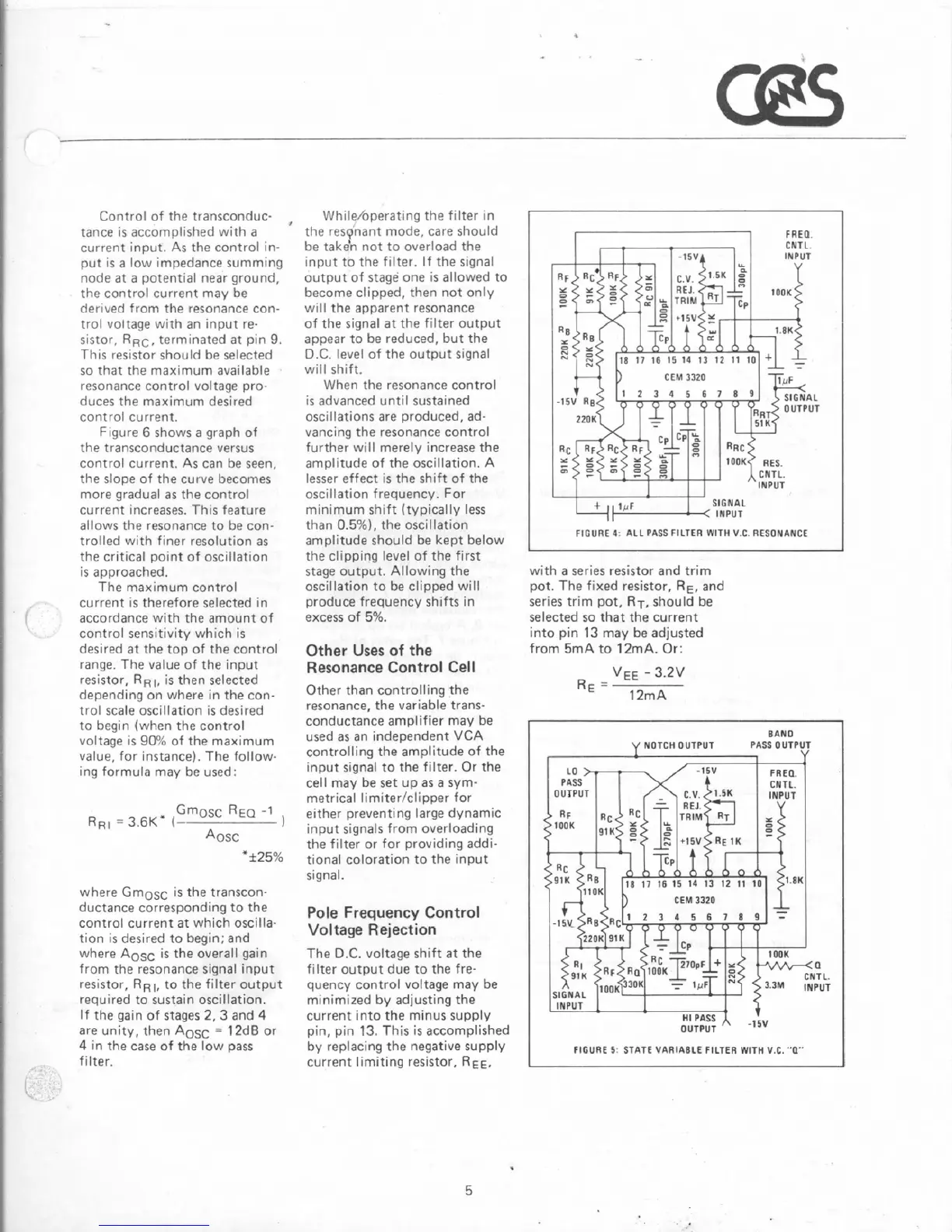
Pole
Frequency
Control
Voltage
Rejection
The
Q.C.
voltage shift at the
filter output due
to
the fre-
quency control voltage
may
be
mlnirnized
by
adjusting
the
current into the minus supply
pin,
pin
73.
This
is
accomplished
by
replacing the negative supply
current limiting resistor.
RE=,
L
T
FlCURE
4
ALL
PASS
FILTER
WlTH
V
C.
RESORANCE
with a series resistor and trim
pot.
The
fixed
resistor,
RE,
and
series
trim
pot,
RT,
should
be
selected
so
that the current
into pin
13
may
be
adjusted
from
5mA
trr
1
TmA.
Or:
FIGURE
5.
5TP.f
E
VIIRIAILE
FILTER
WlTH
V.C.
"U"