Absolute Maximum
Ratings
wher~
Vs
=
KTfq
=
26
mV
@
20'C,
and
where
lc
is
the
total current flowing
into
the
frequency
control pin and must
remain positive for proper
operation
(a
negative input
current will produce
the
same
output as a zero inpuT current).
Since
the frequency control
input
pFn
is
a
virtual ground
summing
node,
any
number
of
pin
16
on
the
3345)
internally
connects
to
the control input
of
the
exponential generator
(base
of Q1
1.
Th~s
output
IS
a
current
and
is
given
by:
control voltages
may
be
summed
simply with input resistors
to
/
this pin.
The
current output of the
multiplier
is
converted to
the
required
drive voltage with
a
resistor from
the
multiplier
output
pin
to ground. For
greatest
multiplier accuracy,
this resistor,
Rs,
should
be
1.8k
and
the current flawing out
of
pin
2,
22VTfRT,
should be
close to the current flowing
out
of pin
1,
3.0/RZ.
Since
the
components
asso-
ciated
w~th the tempco generator
and
multipfier determ~ne the
maximum
voltage excursion
possible
at
the
base
of
Q1,
they
should
be
selected to provide the
desired
frequency control range
of
the
osc~llator.
The
exponen-
tial
generator
itself is capable
of
deliver~ng
a
current
for
charging
and
discharging the timing
capacitor
from
greater than
.5mA
down
to
less
than
the
input bias current
of
the
buffer,
thus allowing for
a
typical fre-
quency
range
greater than
500,000:
7.
The
most
accurate
portion of
this
current range,
from
5QnA
to
1
QOpA,
should
be
used
for
the
most
critical portion
of
the
desired frequency range.
Consideration
of
this
crit~cal
range determines the value of
I
Voltage Between
VCC
and
VEE
Pins
+24V,-0.5V
Voltage Between
VCC
and
Ground Pins
+I
8V,
-0.5V
a
Voltage Berween
VEE
and
Ground
Pins
-16.0V.+0.5V
Voltage Between Frequency Control Pin
or
Reference
Current Pin and Ground
Pin
k6.OV
Voltage Between Multiplier Output
Pin
and Ground
Pin
+6.0V,
-1
V
Current
through Any Pin
k40mA
Storage Temperature Range
-55°C
to
+I
50'C
Operating Temperature
Range
-25'~
to
+75'6
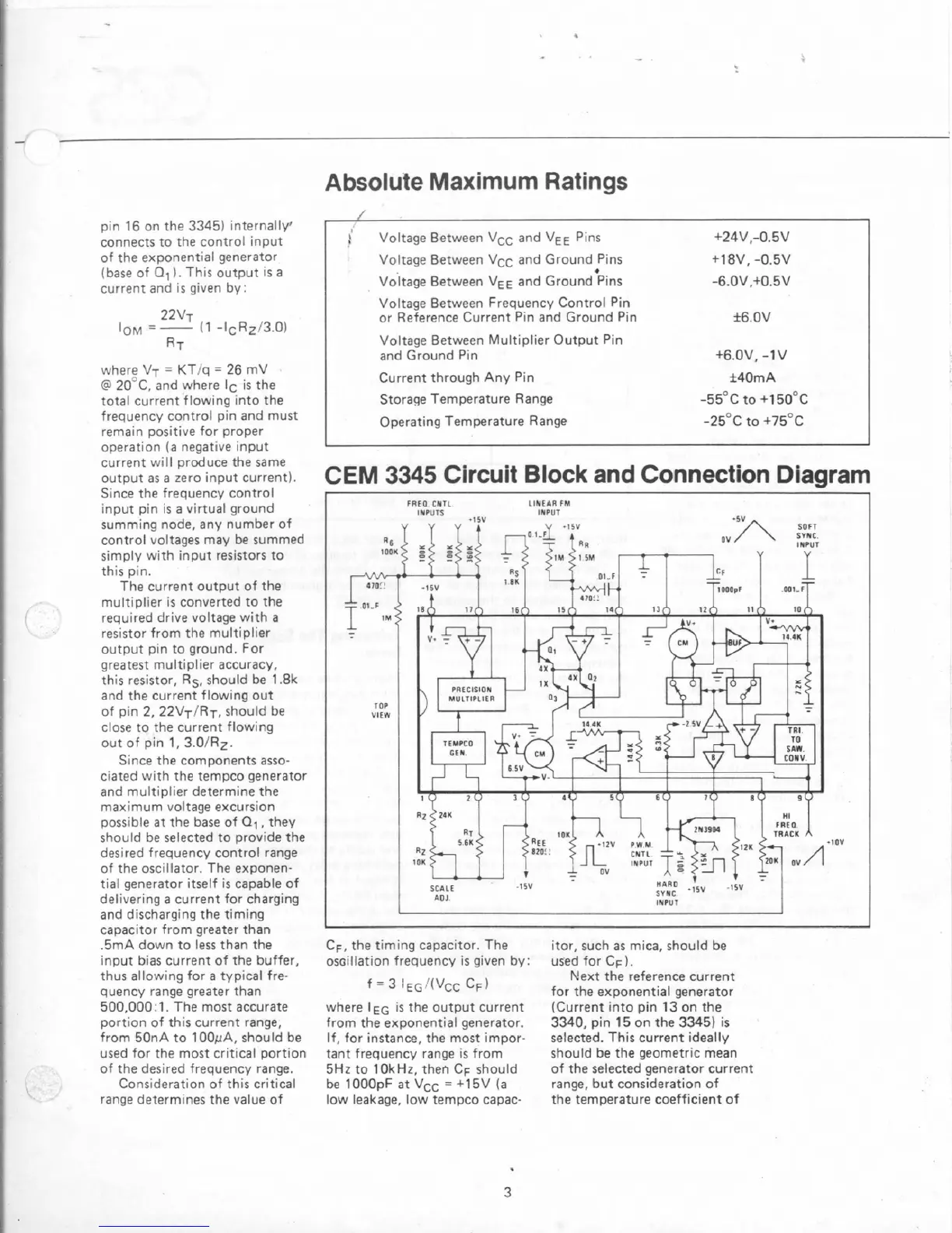
CEM
3345
Circuit
Block
and
Connection
Diagram
FREO
CHTL
LINEN
FM
INPUTS
IHPUl
CF,
the
timing
capacitor.
The
os~illation frequency is given
by:
f
=
3
/(Vcc
CF
1
where
IEG
is the output current
from
the
exponential generator.
If,
for
instance, the
most
irnpor-
tant frequency
range
is.
from
5Hz
to
10kHr.
then
CF
should
be
1000pF
at
VCC
=
+15V
{a
low
leakage, low
tempco
capac-
itor, such
as
mica. should
be
used
for
CF).
Kext
the reference current
for
the exponential generator
(Current into
pin
13
on the
3340,
pin
15
on
the
3345)
is
selected.
This
current ideally
should
be
the geometric
mean
of the selected generator current
range,
but
consideration
of
the temperature coefficient
of