the bias current for
op
amp
A2
usually dictates
a
higher value
for the reference current.
Al-
though this
bias
current has
been temperature compensated,
it could have
a
worst cast
tempco of
1000ppm and maxi-
mum
value
of
400nA.
Under
these
conditions,
a
reference
current
of
1
OpA
through
Q1,
for instance, would
have
a
tempco
of
40ppm.
It
Is
recom-
mended that, in general,
the
reference current
be
selected in
the
3flA
TO
75pA
range.
Since the reference current
pin
is
a
virtual ground summing
node,
the reference current may
be
set up with
a
temperature
stable resistor to
VCC,
or
other
positive stable voltage source.
A
negative current into this pin
will simply gate the exponen-
tial generator
cornpZetely
aff.
With the value
of
CF
and
reference current
now
selected,
the voltage excursion
at
the
multiplier output,
which
drives
the
base
of
Q1,
is
now
detea-
mined
for
the desired frequency
control range.
If
this range
were
1Hz
to
20kW2, the exponential
generator current,
IEG,
would
have to range from 10nA
to
200pA
in
the
above
example.
requiring
the
base drive voltage,
VB,
to
vary
from +180mV to
-78rnV,
since
The
most positive voltage
the
base
of
Ql
occurs when the
~0ntr0l current, IC.
is
zero,
and
is
22vT
RSJRT.
Therefore,
~n
the above example,
RT
=
22V~
1.8KJ.18V
=
5.72K,
and
Rz
=
3.0RT/22VT
=
3OK
nominal.
Finally, since
the
multiplier
output current must
range
from
4100pA
to
-43yA
to
produce
this desired voltage excursion at
the
multiplier output and on the
base
of
Q1,
the
control
input
current,
IC, ranges from
0
to
143pA.
A
resistor from
Vcc
to
the
controt input pin
may
be
used to set the oscillator f
re-
quency
at
some
initial value
with no control voltages applied.
The frequency control scale
is
determined
by
the value of
the input resistor
to
the control
pin, the value
of
the
Q1
base
resistor,
RS,
and the multiplier
current gain. Since the multiplier
current gain,
set
by
the
ratio
of
the pin
2
current
to
pin
1
cur-
rent, should
be
near unity and
RS
should be 1.8K, the control
input resistor is the
co,nponent
which should
be
selected for the
desired
contro! scale. For
the
industry standard
scale
of
1
octavelvolt, the input summing
resistors become
100k.
The
recommended method for
trimming the control scale is
-to tweek the multiplier current
gain
by
adjusting the valuenf
Rz
k20%
about the
nominal
value.
Both the multiplier and the
exponential generator are com-
pensated with
the
470R
-
.01pF
networks
shown
in
the Block
Diagrams and
are
therefore
necessary
In any application.
Since
the bandwidth
of
the
mu
Itiplier extends beyond the
audio range,
it
may be desirable
to limit the bandwidth to re-
duce possible
noise at the base
of
QT,
thereby reducing
FM
noise
and
frequency jitter.
Thrs
1
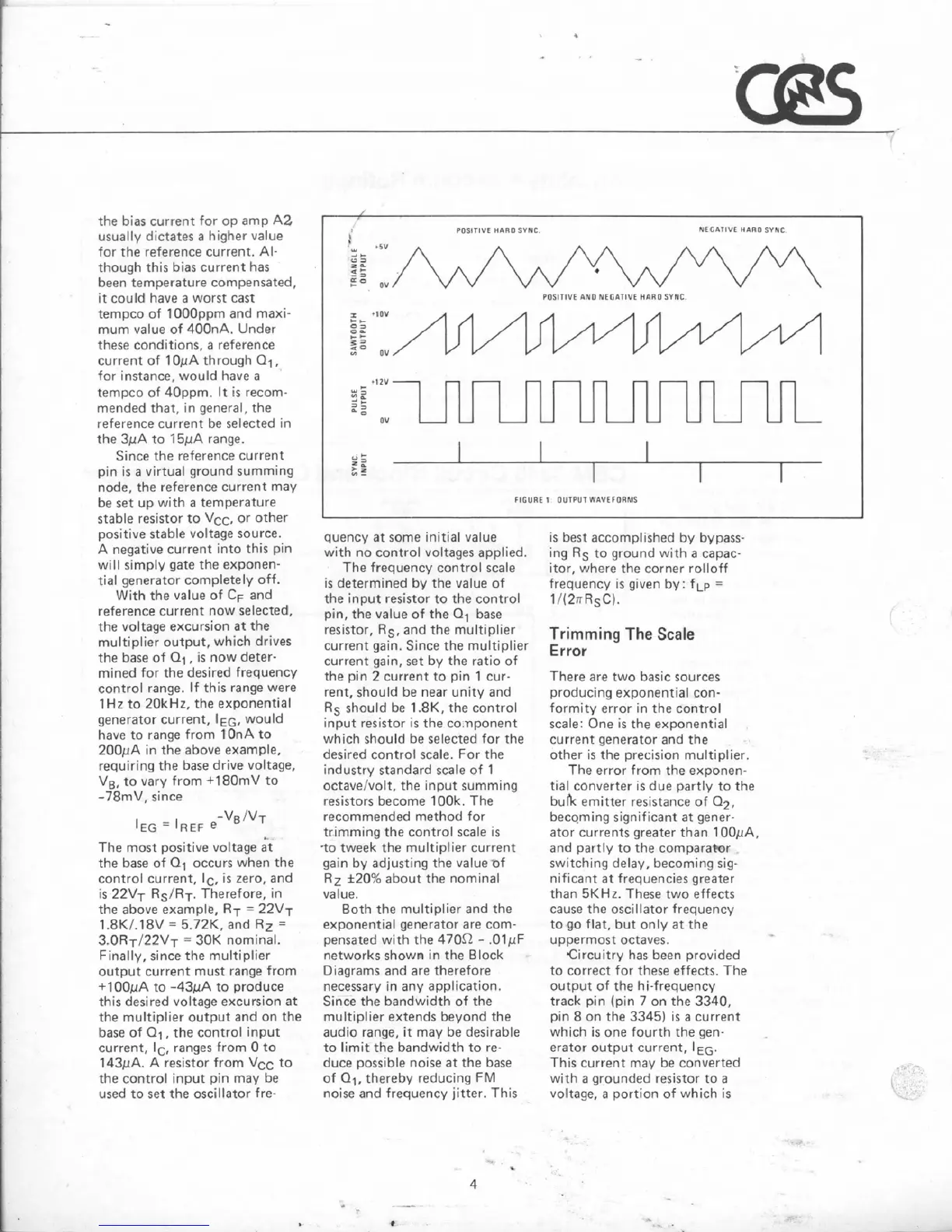
POSITIVE HARM
SYNC
HCCAlfVE
HARO
SYNC
\
*w
+5v
-I-
CI
=
z
k
5
-4=
ov
POSITIUE
AH0 MEGATIUE
HnRO
SYIC
I
tl0V
+
+
m
2
Q
-
+
-
?$
z
*
ov
is best accomplished
by
bypass-
ing
RS
to ground with
a
capac-
itor, where the
corner
rolloff
frequency is
given
by:
fLp
=
1/(2nRSC).
Trimming
The
Scale
Error
+llU-
7
-
-
There
are
two basic sources
producing
exponential
con-
formity error
in
the control
scale:
One
is
the exponential
current generator and the
::
5
E
,
FIGURE
1
OUTPUT
WAVEFORMS
a
i
2;
0v
-
other is
the
precision multiplier.
The
error from the exponen-
tial converter
is
due
partly to the
buk
emitter resistance
of
Q2,
becoming sign~ficant at gener-
ator currents greater than
1
OQpA,
and
partly
to
the compara-r
switching
delay,
becom~ng sig-
nificant
at
frequencies greater
than
5KHz.
These
two
effects
cause the oscillator frequency
toga
flat,
but
only
at the
uppermost octaves.
Circuitry has been provided
to correct for these effects. The
output
of
the hi-frequency
track pin (pin
7
on the
3340,
pin
8
on the
3345)
is
a
current
which
is
one fourth the
gen-
erator output
current,
I
EG.
This current may
be
converted
with
a
grounded resistor to
a
voltage,
a
portion
of
which
is
k
I
-
---
--
--
--
--