then
fed
back
to the control
input pin.
As
the frequency is
~ncreased,
this
feedback
voltage
will tend to sharpen the control
scale, but only at the upper
end, since
the
feedback voltage
becomes
significant
only
at
the
higher
generator currents.
The
amount of
voltage
fed
back
is
adjusted
so
the scale
1s
sharpened
just
enough to
compensate for the inherent
high
end flatness
The method recommended
for trimming
the control
scake
is
as
folqows:
The
hi-frequency
track
adjust
is
first set
so
that
no correction voltage
is
fed to
the control input.
The
oscilla-
tor frequency is
set
around
200Hz and the scale adjust
trimmer
is
adjusted
for the
desired scale factor
Ie.g.
1.000
octaveholt).
Then
the oscillator
frequency is set to around
IOKHz,
and the hi-frequency
track trimmer
IS
adjusted
tor
the
same
scale factor.
The
source
of
error from the
precision multiplier
is
due
to the
multiplier's gain Inominajly
unity) changing
as
the control
input
current
changes.
This type
of
error
causes
the frequency ta
-.
became
increasing!^
sharp or flat
as
the cantrol current is in-
creased. The percentage differ-
ence
in
rnult~plier gains,
and
hence scale factors, at
any
two
inputs to the multiplier
may
be
calculated
as
the
petcentage
errol- glven in
the
specifications
times the difference in
PA
between the two corresponding
outputs.
For
example,
suppose
the
scale were adjusted
for
precisely
1
,octave/voft
at
mid-
range.
At
one
octave above this
adjusted
octave. w~th the
mul-
tqpl~er
output
1OpA
different,
the scale factor could
be
.08%
different worst case. This
would produce
a
volts/octave
error
at
the base of
Q1
of
.OR%
x
l8mY
=
14.4pV,
which would
cause this octave
to
be
-06%
(1
cent)
sharp
or
flat.
At
five
octaves above the adjusted
/
octave,, the scale factor could
be
0.4%
different
worst case, pro-
ducing
a
volts/ocrave
error
of
0.4%
x
18rnV.=
72pV.
This fifth
octave would thus be
0.28%
(5
cents) sharp or flat. Note that
if
octaves
above the
adjusted
octaves were sharp, those
octaves below the
adjusted
octave wou Id become increas-
ingly flat, and
vice versa.
Typically
the error produced
by
the multiplier
is
much less
than the above example.
How-
ever,
if
maintaining
a
tighter
tolerance
is
required for the
particular
application, the mul-
tiplier error
may
be trimmed
out
for each device. The trimming
prbcedure requires that both
RZ
and
RS
be
made
adjustable
f30% about the nominal value;
RZ
is
first adjusted so that the
multiplier gain
is
constant over
the selected input current
range; then
RS
is
adjusted
for
the desired scale factor (adjust-
ing
Rs
will reintroduce
some
error, so
Rz
may
have to be
readjusted).
Should for some reason it
be
desired
not
to
use
the tempera-
ture
compensation circuitry, the
mwltiplicr/ternpco generator
-
may
be
bypassed
simply
by
leaving
pin
I,
pin
2,
and
the
control
rnput
pin
open,
and
applying the control voltage
to
the
base
of
Ql
via
the multiplier
output
pin.
Waveform
Outputs
All waveform outputs are short-
circuit protected
and
may
be
shorted continuously to any
supply without damaging the
device.
Each output, however,
has
differ~ng drive capabilities.
Although
the
triangle output
can sink
at
least
.4mA
and
source
over
several
mA,
care
must
be
exercised
in
loading
th~s
output.
Because
the
output
has
a
finite impedance and
drives the comparator,
a
change
in load will change
the
frequency
of
the
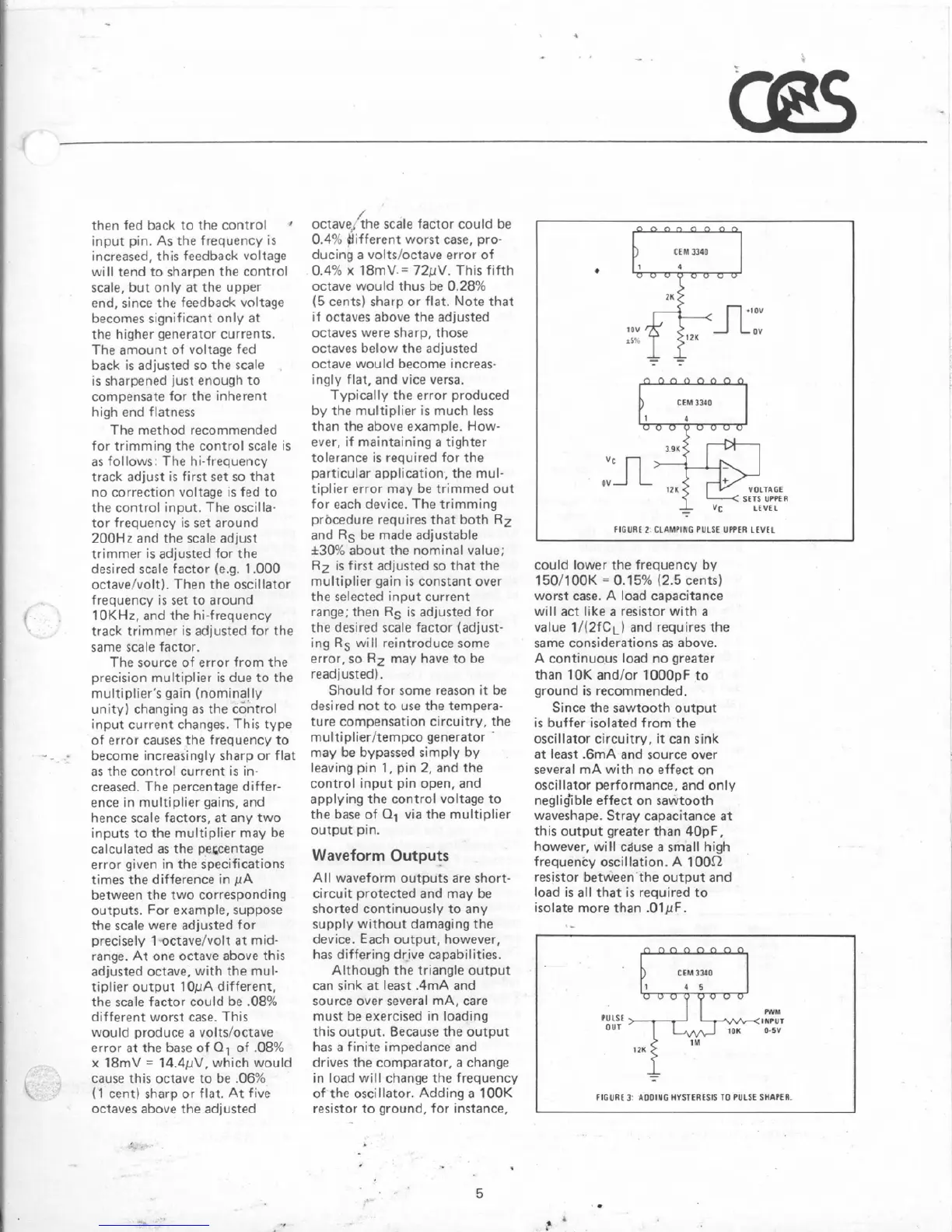
oscillator. Adding
a
ZOOK
resistor to ground, for
Instance,
I
SETS
UPPEA
LCVCL
FIGURE
Z
CLUMPING
PULSE
UPPER
LEVEL
could lower
the
frequency
by
1501100K
=
0.75%
(2.5
cents]
worst
case.
A
load
capacitance
will
act
like
a
resistor with
a
value
1/(2tCL)
and
requires
the
same
considerations
as
above.
A
continuous load no
greater
than
10K
andlor 1000pF to
ground
is
recommended.
Since
the sawtooth output
is
buffer isolated from the
oscillator circuitry,
it
can
sink
at least
-6mA
and
source
over
several
mA
with
no
effect on
OSE~
llator
performance,
and
only
negli$ble effect
on
sawtooth
waveshape. Stray capacitance
at
this output greater than
40pF.
however, will cduse
a
small high
frequency oscillation,
A
10012
resistor between'the output and
load
is
all that
is
required to
isolate more than
.OlpF.
I
FIGURE
I
&D01NG
HYSTERESIS
TO
PULSE
SHAPER.