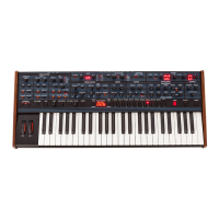
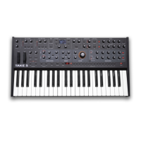
The
mixer
knobs
are
simply attenuators which
set
the
level
of
selected
OSC
A
(R1132),
OSC
B
(R1133) waveforms and
NOISE
(R1134) sent to the filter. R1147
and
R1E4X
sum
the
adjusted
oscillator outputs into the filter.
The white noise
source
is created
by
reverse-biasing the emitter-base junction
of
PNP
4103
far
above
its
breakdown threshold.
(To
increase
the
noise
output
with
certain
later
batches
of
transistors, R1120
was
changed from lOOK
to
200K.) C131 ac-couples
the resulting noise to non-inverting
amp
U107-14,
which
has
a
gain
of
3
(1+Rlll6/-
R1117).
NOISEJEXT
input switching
is
accomplished
by
57,
which
is
a
trstereoql
jack
wired
for
use.
With
no
plug
inserted,
noise
connects through the
!'tipM
switch contact to
R
1134
MIXER
NOISEJEXT
knob. Connecting
an
external
mono
phone
plug
to
57
AUDIO
IN
bypasses
the
noise
with
the
external audio,
and
also grounds the sleeve contact on
the
jack,
This creates
the
active-low -EXT signal
which
enables the gate
select
logic
and
audio gate comparator (both'discussed below),
U
108-1
~oise/Ext
Preamp
is
an
ac-coupled non-inverting microphone-type preamplifi-
er
with
a
frequency
roll-off
just
above
20
kHz.
R1152
sums
its
output
into
the
filter.
The
Preamp
also drives
U107-8
Envelope
Follower,
which
rectifies
the
external audio
amplitude
from
0
to
+
15
Vdc,
and
also
drives
U107-1
Audio
Gate
(AGATE)
Comparator
(CPR).
With
no
audio
input, UE07-1
-AGATE
is
high (+15V).
When
the
rectified
envelope across
R1115
exceeds
the
threshold
set
by
divider
R1112
and
R1114 (with
-
EXT
grounded),
-AGATE
goes
low.
The
application
of
the
-AGATE
signal
is
discussed
below.
To
prevent oscillation around the
threshoId
point,
C130 briefly
retains
the
peak
voltage.
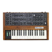
2-5
FILTER
The Pro-One's
low-pass filter
is
based
on
the
CEM
3320
integrated
voltage-controlled
filter
CVCF).
The
control
scale
for
its
cutoff
frequency matches
the VCO
scale
of
1v1ocr.
There are
many
sources
of
filter
cutoff
CV
into
Ul
1
1-
12. Working
back
from
U
I
15-8
inverting
FILTER
CV
SUMMER,
Rll88
CUTOFF
knob
is
summed through R1171.
5121
MODULATION
TO
FILTER
selects the modulation
buss
summed through
R
11
70.
R1173
sums
the adjusted output
of
R119k FILTER
KEYBOARD
AMOUNT
knob,
which
is
normally the keyboard
voltage
connected
through
J6
FILTER
CV
IN.
J6,
of
course,
allows
for
external filter cantrol independentay
of
the
keyboard. (When troubleshooting
for
"no
filter keyboard voltage," check the contacts
on
this
jack.)
R1172
connects the
FILTER
ENVELOPE
GENERATOR
output
from
Ull6-2, adjusted
by
R1190
FILTER
ENVELOPE
AMOUNT.
C~ote"
that it
is
redundant to route the filter
envelope
both
through Rll9O
-
and
through
S
12
1.
See
below, under
MODULPTION
SOURCES.)
Finally,
R
11
73
sets
the
basic control range.
I
/'
The
filter output,
Ulll-10
is ac-coupled by
C143
to
non-inverting
buffer
Ul10-7,
which
has
a
gain of
2.4
(RlE44/R1146). This
buffer
drives
both
the
Final
VCA
stage
and,
through divider R1162JR1163,
the
"resonance
gain
celltqnternal to the
3320,
which actually
feeds
filter
output back to the
input
of
stage
A.
The
gain
of
this
internal
amp
is
adjusted
by
R
1189
FILTER
RESONANCE
knob through
R
1
157.