CEM
3340
/
CEM
3345
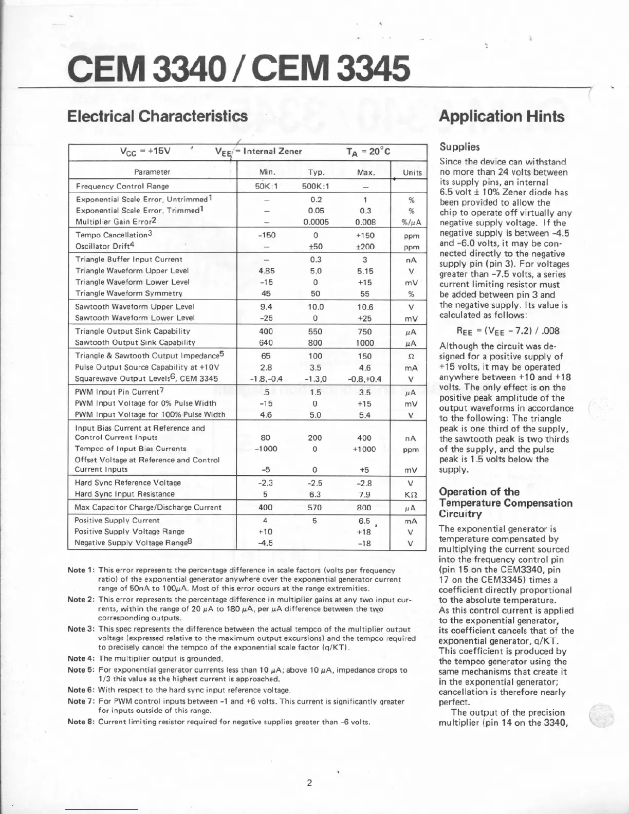
Electrical
Characteristics
Application
Hints
Triangle Waveform Uppsr Level
Triangle Waveform Lower Level
/
Supplies
Since the
device
can withstand
no
more
than
24
volts between
its
suppty
pins,
an
internal
6.5 volt
k
10%
Zener
diode
has
been provided to allow the
chip to operate
off
virtually any
negative supply voltage. If the
negative supply is between
-4.5
and
-6.0
volts. it may
be
con-
nected directly
to
the
negative
supply
pin
(pin 3). For voltages
greater than
-7.5
volts,
a
series
current limiting resistor must
be added between
pin
3 and
the negative supply.
Its
value is
calculated
as
follows:
Although
the
circuit
was
de-
signed for
a
positive supply of
+I
5
volts,
it
may
be operated
anywhere between
4-10
and +I8
volts.
The
only
effect is
on
the
positive
peak
amplitude of the
output waveforms in accordance
to
the following:
The
triangle
peak is one third
of
the
supply,
the sawtooth peak is two thirds
of the supply, and
the
pulse
peak is
1.5
volts below
the
SUPP~Y.
Note
1
:
This error represents
the
percentage difference in scale Tactors (volts per frequencv
ratiol
of
the exponential generator anywhere aver the exponential generator
current
range
of
50nA to
100vA.
Most
of
this error occurs
at
the range extremities,
Note
2:
This
error represents
the
percentage d~fference in multiplier gains;
at
any two input cur-
rents, within the
range
of
20
FA
to
180
pA,
per
pA
difference between
the
two
corresponding
outputs.
Note
3;
This
spec
represents the difference between
the
actual tempco of
the
rnultipl~er output
voltage
(expressed
relat~ve
to
the
maximum output excursions) and the ternpco required
to precisely cancel the tempco
of
the exponentla1 scale factor
(qtKT1.
Note
4:
The multiplier output is grounded,
Note
5:
For
exponential generator currents less
than
10
PA;
above
10
PA,
impedance drops
to
T
13
this
value
as
the
highest
current
IS
approached.
Note
6:
With respsct to the hard sync Input reference voltage.
Note
7:
For
PWM
control Inputs between
-1
and
+6
volts.
This
current
is
significantly greater
for
inputs
outside
of
thls
range.
Mate
81:
Current limiting resistor required for negative supplies greater than
4
volts.
Operation of
the
Temperature
Compensation
Circuitry
The
exponential generator is
temperature compensated
by
multiplying the current
sourced
into the frequency control pin
(pin
15
on
the
CEM3340,
pin
17
on
the
CEM3345)
times
a
coefficient directly proportional
to the absolute temperature.
As
this control current is applied
to the exponential generator,
its coefficient cancels
that
of
the
exponential generator,
q/KT.
This
coefficient is produced
by
the
tempca
generator
using
the
same
mechanisms
that
create
it
in the exponential generator;
cancellation
is
therefore nearly
perfect.
The output
of
the
precision
multiplier (pin
14
on
the
3340,