5
Electrical installation
Electrical connections
Assembly and Operating Instructions – MAXO-MS/M/SM-GIOP Sensor Module
25
No. Name Function
1 +24V DC24V supply
2 n.c. Not assigned
3 0V24 0V24 reference potential
4 n.c. Not assigned
5 RX+ Transmit line (+)
6 RX- Receive line (+)
7 TX+ Transmit line (-)
8 TX- Receive line (-)
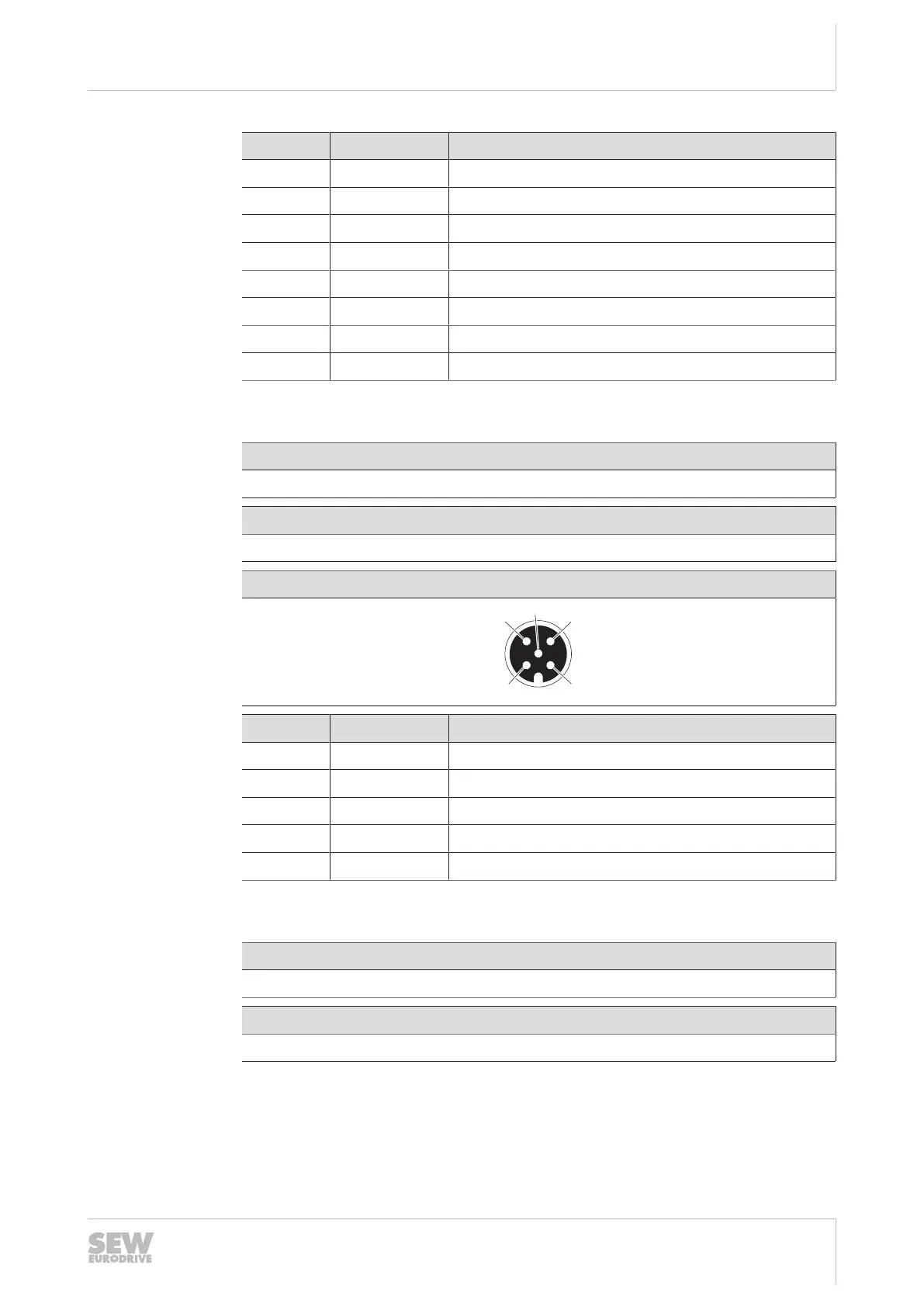
5.1.4 X4111_11/12: CAN interface
Function
CAN interface
Connection type
Connection M12, 5-pin, female, A-coded
Connection diagram
No. Name Function
1 SHLD Shield
2 n.c. Not assigned
3 0V24 0V24 reference potential
4 CAN_H CAN high
5 CAN_L CAN low
5.1.5 X1512: DC24V supply
Function
DC24V device supply input
Connection type
Connection M12, 4-pin, male, A-coded
26868113/EN – 03/2021
 Loading...
