Operating Instructions – MOVITRAC® LT Option Cards
13
3
Preliminary work
Mechanical Installation
3 Mechanical Installation
3.1 Preliminary work
• Turn the drive off and wait at least 10 minutes before installing the option card.
3.2 Installation procedure
• Insert the option card into the MOVITRAC
®
LT control terminal strip.
• Tighten all 11 terminal screws on the MOVITRAC
®
LT to ensure good electrical
contact.
WARNING
Dangerous voltages are present in the output terminals and the cables and motor
terminals connected to them when the unit is switched on.
The unit is not necessarily deenergized when the LEDs and the 7-segment display
are off. Dangerous voltages may also be present when the unit is inhibited and the
motor at a standstill.
High voltages are also present in the terminals and within the drive for up to 10 min-
utes after the electrical supply has been disconnected.
Severe or fatal injuries from electric shock.
• Disconnect and isolate the MOVITRAC
®
LT from the electrical supply at least
10 minutes before commencing any work on it.
TIP
When installing an option card into the following units, support the option card whilst
tightening the terminal screws.
•MOVITRAC
®
LTP, Size 1
•MOVITRAC
®
LTP IP55 (all sizes)
•MOVITRAC
®
LTE-B (all sizes)
TIP
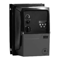
Once the option cards have been installed and fully wired into an IP55 / NEMA 12 drive,
the board must be bent slightly in a downwards direction to enable the front cover to be
closed. This does not affect the function of the option board.
Phone: 800.894.0412 - Fax: 888.723.4773 - Web: www.clrwtr.com - Email: info@clrwtr.com

 Loading...


