Operating Instructions – MOVITRAC® LT Option Cards
23
6
Electrical interface
Third relay output
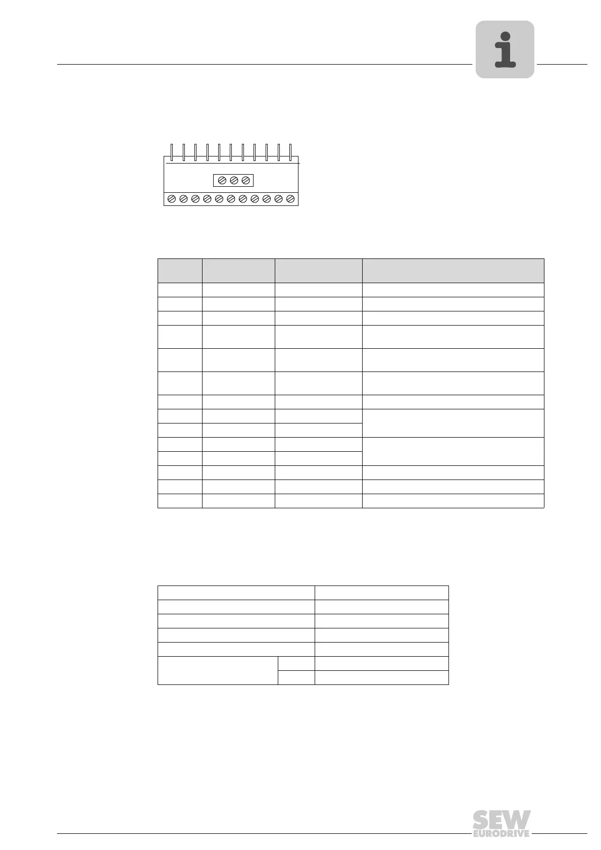
6.3 Electrical interface
6.4 Technical data
65689AXX
Terminal
no.
Signal Connection Description
1 +24 V +24 V ref out Ref. to activate DI1 – DI3 (100 mA max.)
2 DI 1 Digital input 1 Not affected
3 DI 2 Digital input 2 Not available if P2-01 = 20, 21 or 22
4 DI 3 Digital input 3 /
thermistor contact
Not affected
5 +10 V +10 V ref out 10 V ref for analog input
(pot supply +, 10 mA max., 1 K Ω min.)
6 AI / DI Analog input (12 bit) /
Digital input 4
0–10 V, 0–20mA, 4–20 mA
"Logic 1" input voltage range: DC 8 – 30 V
7 0 V 0 V common 0 V ref for analog input (pot supply –)
8 Relay 2 contact Relay contact N.O. relay contact (AC 250 V / DC 30 V @ 1 A)
9 Relay 2 common Relay common
10 Relay 1 contact Relay contact N.O. relay contact (AC 250 V / DC 30 V @ 1 A)
11 Relay 1 common Relay common
12 Relay 3 contact Relay contact N.O. relay contact
13 Relay 3 common Relay common –
14 Relay 3 contact Relay contact N.C. relay contact
12
3456
12 13
7891011
14
Max. relay switching voltage AC 250 V / DC 220 V
Max. relay switching current 1 A
Max. input voltage DC
±50 V
Conformity IP00, UL94V-0
Environmental –10 – +50 °C
Dimensions [mm] 56 × 24 (not pins) × 14
[in] 2.20 × 0.98 (not pins) × 0.56
Phone: 800.894.0412 - Fax: 888.723.4773 - Web: www.clrwtr.com - Email: info@clrwtr.com

 Loading...