16
Operating Instructions – MOVITRAC® LT Option Cards
4
Electrical interface
Second Analog Input
4.4 Electrical interface
64746AXX
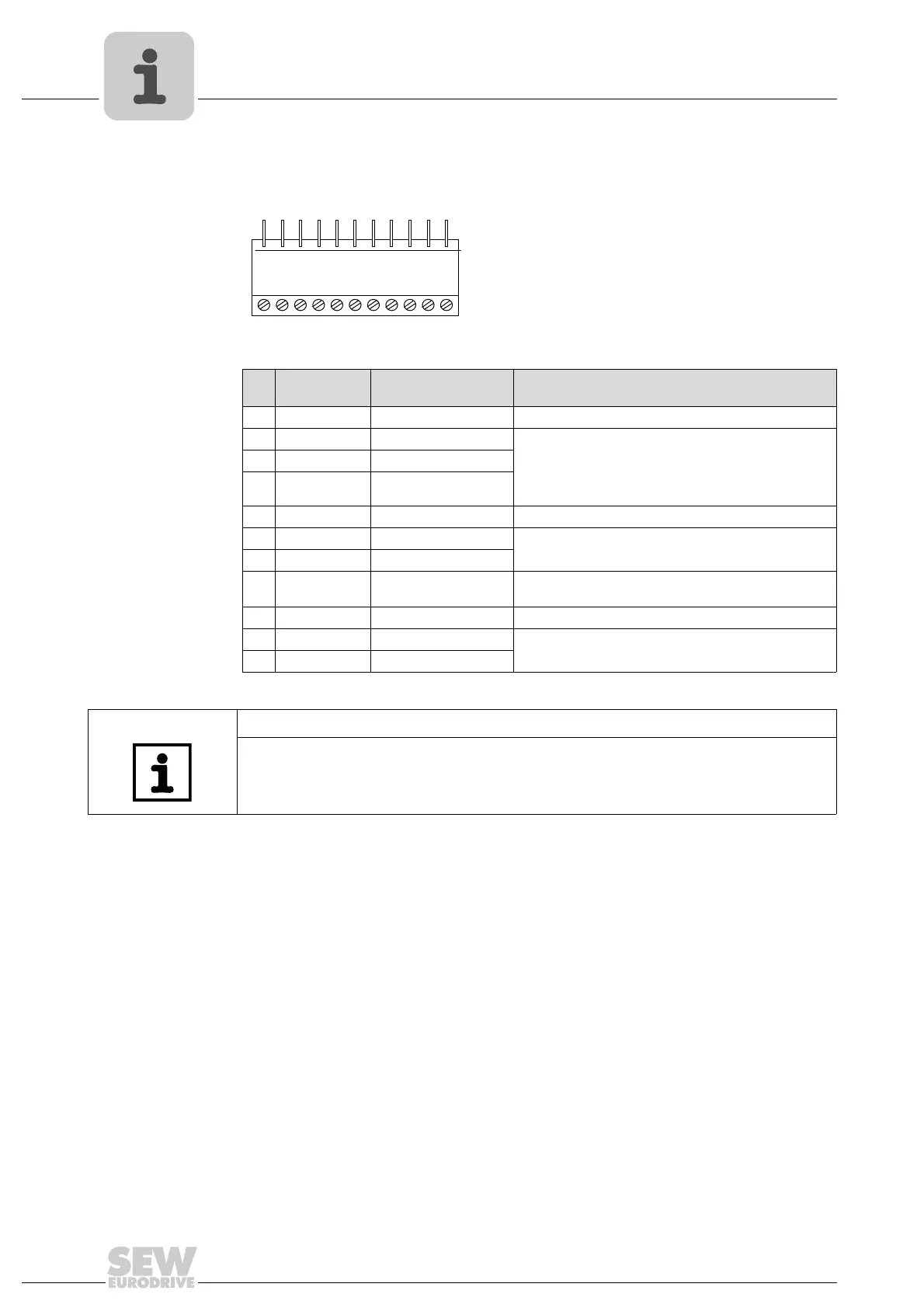
Pin
no.
Signal Connection Description
1 0 V 0 V common for AI Ref. to activate DI1 – DI3 (100 mA max.)
2 DI1 Digital Input 1 Positive logic
’Logic 1" input voltage range: DC 8 – 30 V
"Logic 0" input voltage range: DC 0–2V
Compatible with PLC-requirement when 0 V is con-
nected
3 DI 2 Digital Input 2
4 DI3 Digital Input 3
5 +10 V +10 V 10 V ref for AI / DI
6 AI 1 Analog Input 1 0 – 10 V, 0 – 20 mA
7 AI 2 Analog Input 2
8 AO / DO Analog Output (10-bit) /
Digital output
0 – 10 V, 20 mA analog
24 V / 20 mA digital
9 0 V 0 V common 0 V ref for analog output
10 Relay contact Relay contact N.O. relay contact (AC 250 V / DC 30 V @ 1 A)
11 Relay common Relay common
12
3456 7891011
TIP
The signal connected to Digital Input 3 is used to switch between Analog Input 1
(terminal 6) and Analog Input 2 (terminal 7).
Phone: 800.894.0412 - Fax: 888.723.4773 - Web: www.clrwtr.com - Email: info@clrwtr.com

 Loading...