Operating Instructions – MOVITRAC® LT Option Cards
19
5
Electrical interface
Second relay output
5.3 Electrical interface
5.4 Technical data
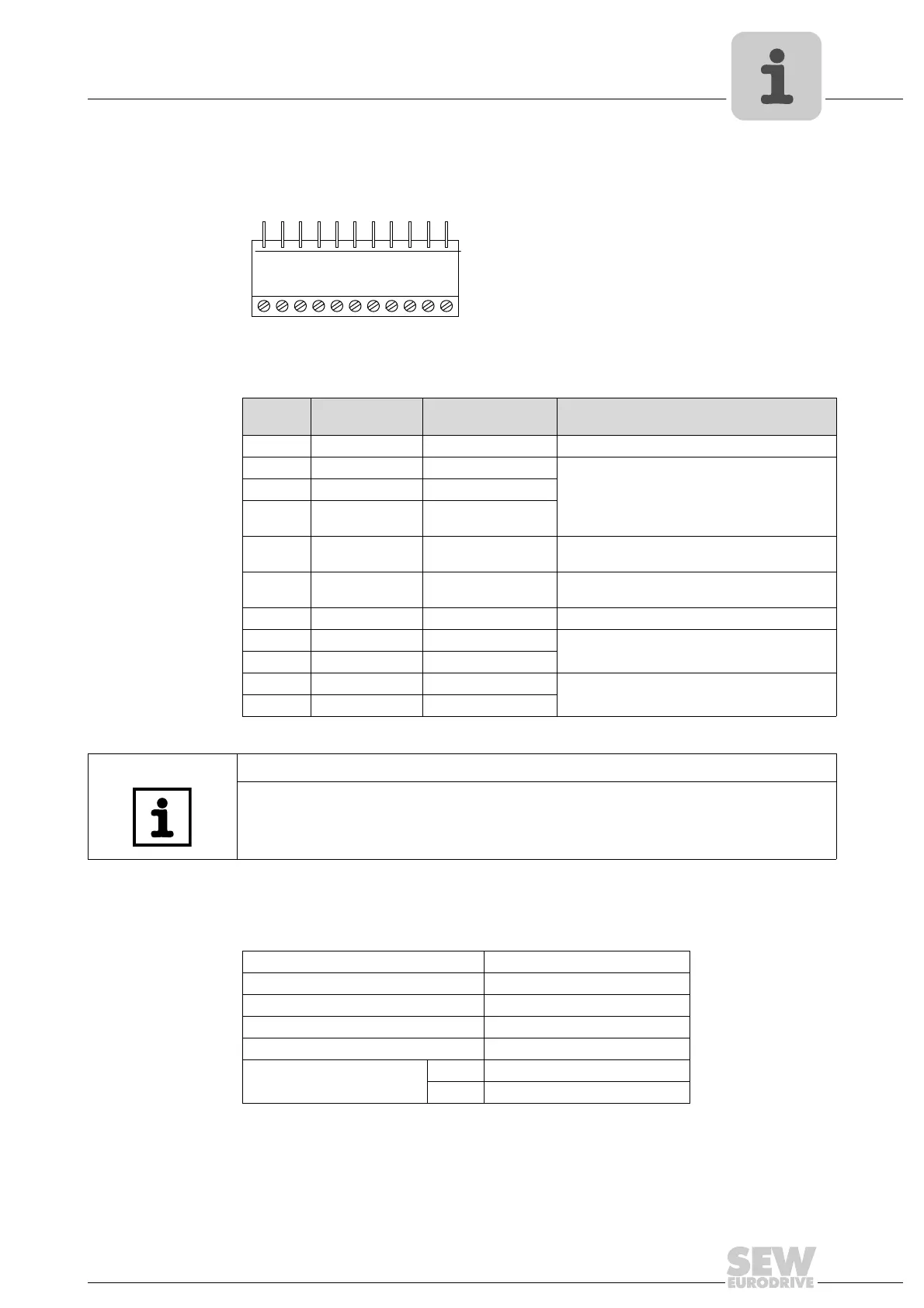
64746AXX
Terminal
no.
Signal Connection Description
1 +24 V +24 V ref out Ref. to activate DI1 – DI3 (100 mA max.)
2 DI 1 Digital input 1 Positive logic
"Logic 1" input voltage range: DC 8 – 30 V
"Logic 0" input voltage range: DC 0 – 2 V
Compatible with PLC requirement when 0 V is
connected.
3 DI 2 Digital input 2
4 DI 3 Digital input 3 /
thermistor contact
5 +10 V +10 V ref out 10 V ref for analog input
(pot supply +, 10 mA max., 1 K Ω min.)
6 AI / DI Analog input (12 bit)
Digital input 4
0–10 V, 0–20mA, 4–20 mA
"Logic 1" input voltage range: DC 8 – 30 V
7 0 V 0 V common 0 V ref for analog input (pot supply –)
8 Relay 2 contact Relay contact N.O. relay contact (AC 250 V / DC 30 V @ 1 A)
9 Relay 2 common Relay common
10 Relay 1 contact Relay contact N.O. relay contact (AC 250 V / DC 30 V @ 1 A)
11 Relay 1 common Relay common
12
3456 7891011
TIP
The second relay output contacts are available on terminals 8 & 9. This relay utilises
the drive’s analog / digital output for operation. Therefore the analog input is not avail-
able when this module is fitted.
Max. relay switching voltage AC 250 V / DC 220 V
Max. relay switching current 1 A
Max. input voltage DC
±50 V
Conformity IP00, UL94V-0
Environmental –10 – +50 °C
Dimensions [mm] 56 × 24 (not pins) × 14
[in] 2.20 × 0.98 (not pins) × 0.56
Phone: 800.894.0412 - Fax: 888.723.4773 - Web: www.clrwtr.com - Email: info@clrwtr.com

 Loading...