34
Operating Instructions – MOVITRAC® LT Option Cards
9
Electrical interface
Converter card
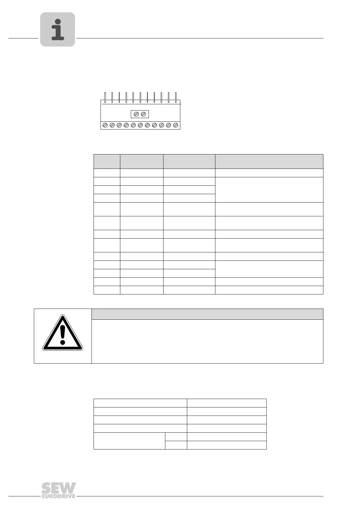
9.3 Electrical interface
9.4 Technical data
64748AXX
Terminal
no.
Signal Connection Description
1 Neutral Neutral Must not be connected to 0 V
2 DI 1 Digital input 1 AC 80 – 250 V, 68 k Ω impedance
3 DI 2 Digital input 2
4 DI 3 Digital input 3
5 +10 V +10 V ref out 10 V ref for analog input
(pot supply +, 10 mA max., 1 K Ω min.)
6 AI / DI Analog input (12 bit)
Digital input 4
0 – 10 V, 0 – 20 mA, 4 – 20 mA
"Logic 1" input voltage range: DC 8 – 30 V
7 0 V 0 V common 0 V ref for analog input (pot supply –)
8 AO / DO Analog output (10 bit)
Digital output
0–10V, 20mA analog
24 V / 20 mA digital
9 0 V 0 V common 0 V ref for analog output
10 Relay 1 contact Relay contact N.O. relay contact (AC 250 V / DC 30 V @ 1 A)
11 Relay 1 common Relay common
12 Neutral Neutral Must not be connected to 0 V
13 DI4 Digital input 4 AC 80 – 250 V, 68 k Ω impedance
12
3456
12 13
7891011
NOTICE
The digital input terminals are optically isolated from the remaining terminals and the
drive terminals. Terminals 1 and 12 are connected internally and must not be connect-
ed to terminal 7 (0 V / GND) as this could result in damage to the option card.
Max. relay switching voltage AC 250 V / DC 220 V
Max. relay switching current 1 A
Conformity IP00, UL94V-0
Environmental 0 – +50 °C
Dimensions [mm] 56 × 24 (not pins) × 14
[in] 2.20 × 0.98 (not pins) × 0.56
Phone: 800.894.0412 - Fax: 888.723.4773 - Web: www.clrwtr.com - Email: info@clrwtr.com

 Loading...