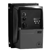
Operating Instructions – MOVITRAC® LT Option Cards
27
7
Technical data
Two indicator relay
7.4 Technical data
7.5 Operation in MOVITRAC
®
LTE-B
7.5.1 Programming the first relay output
For typical operation set parameter P-18 to 1. For example, relay 2 closed on enable
(drive running, green LED) and relay 1 closed when drive tripped (red LED).
Use the following information to set parameter P-18 for other types of relay output.
Since the 1st relay output (fitted within the drive) is programmed using parameter P-18
in the drive, 2 completely independent relay outputs are available. The following options
are supported for relay 1:
7.5.2 Programming the second relay output
The second relay output only has 1 practical setting:
Max. relay switching voltage AC 250 V / DC 220 V
Max. relay switching current 1 A
Max. input voltage DC
±50 V
Conformity IP00, UL94V-0
Environmental –10 – +50 °C
Dimensions [mm] 56 × 24 (not pins) × 14
[in] 2.20 × 0.98 (not pins) × 0.56
P-18
0: Relay 1 is closed when drive is disabled
1: Relay 1 is closed when drive is tripped
2: Relay 1 is closed when drive output is not at set speed
3: Relay 1 is closed when drive is switched off
4: Relay 1 is closed when drive output is not at maximum speed
5: Relay 1 is closed when drive output is not in overload
P-18
1: Relay 2 is closed when drive is running
TIP
The two indicator relay (HVAC) option card only operates when P-15 is set to a number
where DI01 sets the enable signal for the drive, e.g. in Terminal Mode P-15 = 0 – 4, 6,
8 or 12. Further information can be found in the MOVITRAC
®
LTE-B Operating Instruc-
tions.
All other I/Os are not affected.
Phone: 800.894.0412 - Fax: 888.723.4773 - Web: www.clrwtr.com - Email: info@clrwtr.com

 Loading...


