Manual – MOVI-PLC® advanced DHE41B/DHF41B/DHR41B Controller
17
4
Installing the MOVI-PLC® advanced DHE41B controller
Mounting/Installation Instructions
4.3.2 Connection of binary inputs and outputs (connector X31)
Connector X31 provides 8 binary inputs or outputs (e.g. for controlling external actua-
tors/sensors).
You can define the binary inputs and outputs in the PLC editor of the MOVITOOLS
®
MotionStudio software.
Binary inputs • The binary inputs are electrically isolated by optocouplers.
• The permitted input voltages are defined according to IEC 61131.
+13 V ... +30 V = "1" = Contact closed
–3 V ... +5 V = "0" = Contact open
Interrupt inputs • You can use binary inputs X31:6 to X31:10 as interrupt inputs. The response time
until the ISR (interrupt service routine) is processed is less than 100 ms.
Binary outputs • The binary outputs are electrically isolated by optocouplers.
• The binary outputs are short-circuit proof but not interference-voltage-proof.
• The maximum permitted output current is 150 mA per binary output. All eight binary
outputs can be operated simultaneously with this current.
• To avoid the danger of maximum voltage peaks, you may not connect inductive loads
to the supply voltage or to the binary inputs or outputs without free-wheeling diodes.
Cable specification • Only connect cables with a minimum core cross section of 0.25 mm
2
(AWG23) and
a maximal core cross section of 1 mm
2
(AWG18). IEC 60999 does allow clamping
without conductor end sleeves.
• Choose the type and core cross section of the connected cable in dependency of the
required cable length and the load expected from your application.
For more information on binary inputs or outputs, refer to chapter "Technical Data" on
page 61.
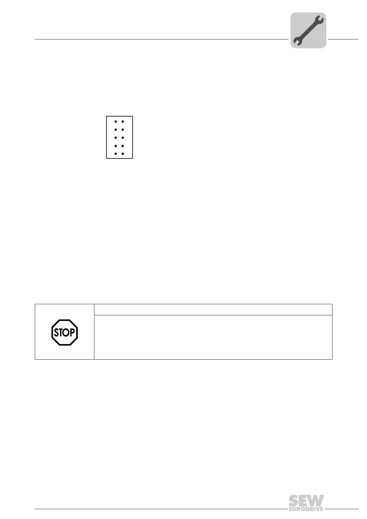
61018AXX
Figure 3: 12-pin connector for connecting binary inputs and outputs
X31
1
3
5
7
9
2
4
6
8
10
STOP!
The supply voltage must be present on X31:1/2 for using the binary inputs and outputs.
The MOVI-PLC
®
controller can be damaged. In this case, the specified function of the
binary inputs and outputs is no longer ensured.
If the supply voltage is stopped, you must turn off all other current supplies to X31:1 ...
10, e.g. the DC 24 V from switches and sensors at the binary inputs.