Manual – MOVI-PLC® advanced DHE41B/DHF41B/DHR41B Controller
19
4
Installing the MOVI-PLC® advanced DHE41B controller
Mounting/Installation Instructions
Cable length • The permitted total cable length depends on the baud rate setting of the system bus:
– 125 kbaud → 500 m
– 250 kbaud → 250 m
– 500 kBaud → 100 m
– 1000 kbaud → 40 m
Terminating
resistor
• Switch on the system bus terminating resistor at the start and end of the CAN 2 sys-
tem bus connection (MOVIDRIVE
®
B, DIP switch S12 = ON; MOVITRAC
®
B, DIP
switch S1 = ON). For all other devices, switch off the terminating resistor
(MOVIDRIVE
®
B, DIP switch S12 = OFF; MOVITRAC
®
B, DIP switch S1 = OFF). If
the MOVI-PLC
®
advanced DH.41B controller is, for example, located at the end of
the CAN 2 system bus, you have to connect a terminating resistor of 120 O between
pins X32:2 and X32:3 (for CAN 1: terminating resistor between pins X33:2 and pin
X33:3).
4.3.4 Connection of the RS485 interface (connector X34)
You can connect one of the following devices to the RS485 interfaces COM1/2 (connec-
tor X34):
• DOP11A operator terminals
• Gearmotor with integrated frequency inverter MOVIMOT
®
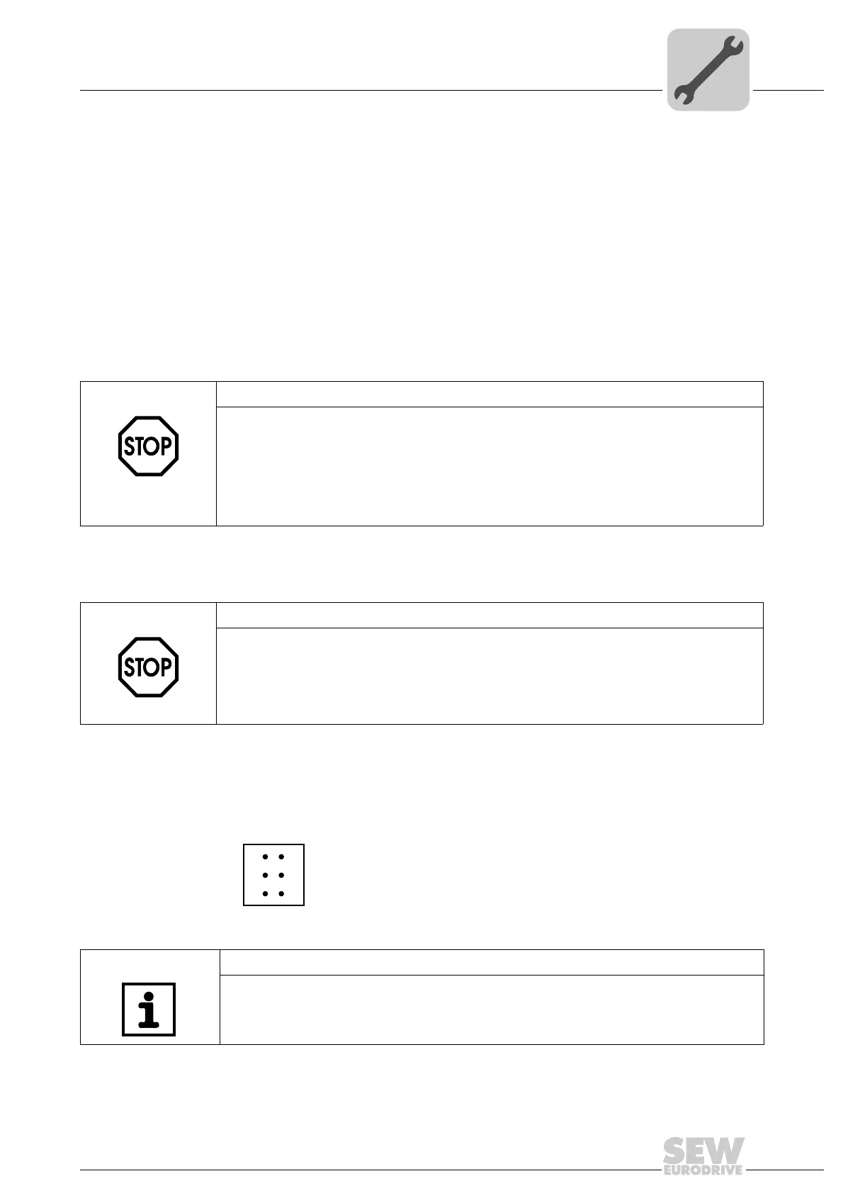
STOP!
•There must not be any potential displacement between the units connected via the
CAN 2 system bus.
•There must not be any potential displacement between the units connected via the
CAN 1 system bus.
• Take suitable measures to avoid potential displacement, such as connecting the
unit ground connectors using a separate cable.
STOP!
• There must not be any potential displacement between the units connected via the
RS485. Take suitable measures to avoid a potential displacement, e.g. by connect-
ing the unit ground connectors using a separate lead.
• Dynamic terminating resistors are installed. Do not connect any external termi-
nating resistors.
63207AXX
Figure 5: 6-pole connector for connecting the RS485 interfaces COM1/2
X34
1
3
5
2
4
6
NOTE
For more information on how to connect the DOP11B operator terminal, refer to the
chapters "Installation" and "Pin assignment" in the "DOP11B Operator Terminals" sys-
tem manual.