32
Manual – MOVI-PLC® advanced DHE41B/DHF41B/DHR41B Controller
4
Installing the MOVI-PLC® advanced DHR41B controller
Mounting/Installation Instructions
4.5 Installing the MOVI-PLC
®
advanced DHR41B controller
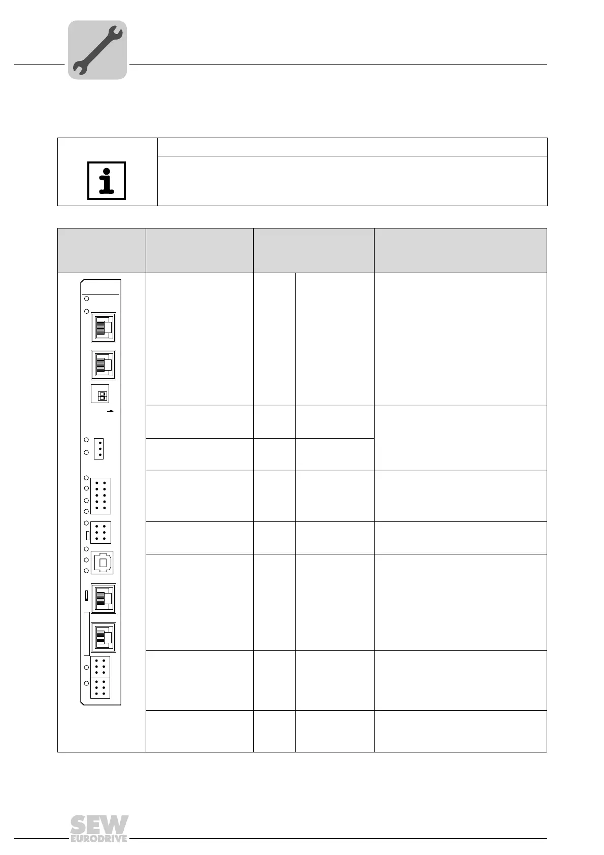
4.5.1 Function description of the terminals, DIP switches and LEDs
NOTE
The connections identical with DHE41B and DHF41B are described in the sections "In-
stallation of the MOVI-PLC
®
advanced DHE41B/DHF41B controller".
Front view
MOVI-PLC
®
advanced DHR41B
controller
Designation
LED
DIP switches
Terminal
Function
63362AXX
LED LED 1
LED 2
LED 3
LED 4
LED 5
LED 6
LED 7
LED 8
LED 9
LED 10
LED 11
LED 12
LED 13
LED 14
CAN 1 status
CAN 2 status
IEC progr. status
PLC status
User LED
DIO6/7
DIO4/5
DIO2/3
DIO0/1
24V / I/O OK
-
-
Status of CAN 1 system bus
Status of CAN 2 system bus
Status of control program
Status of control firmware
Freely programmable
Status input or output DIO6/7
Status input or output DIO4/5
Status input or output DIO2/3
Status input or output DIO0/1
Status of voltage supply I/O
Reserved
Reserved
Bus status
Bus status
Connector X30-1:
Ethernet 3
(RJ45 socket)
X30-1
Standard Ethernet assignment
Connector X30-2:
Ethernet 4
(RJ45 socket)
X30-2
DIP switches 2
0
, 2
1
2
0
2
1
ON
OFF
ON
OFF
Default IP address (192.168.10.4)
Stored IP address / DHCP
EtherNet/IP / Modbus TCP/IP
PROFINET
Connector X38:
SafetyBus
(plug-in terminals)
X38:1
X38:2
X38:3
Reserved
Reserved
Reserved
Terminal X31:
Binary inputs and out-
puts
(plug-in terminals, color:
BK))
X31:1
X31:2
X31:3
X31:4
X31:5
X31:6
X31:7
X31:8
X31:9
X31:10
+24 V input
REF24V
DIO 0
DIO 1
DIO 2
DIO 3
DIO 4
DIO 5
DIO 6
DIO 7
Voltage input DC+24 V
Reference potential for binary signals
Binary input or output
Binary input or output
Binary input or output
Binary input or output
Binary input or output
Binary input or output
Binary input or output
Binary input or output
Terminal X34:
RS485 interfaces COM1,
COM2
(plug-in terminals, color:
BK)
X34:1
X34:2
X34:3
X34:4
X34:5
X34:6
RS+
RS+ insulated
RS–
RS– insulated
DGND
GND insulated
Signal RS485+ (COM 1)
Signal RS485+ insulated (COM 2)
Signal RS485– (COM 1)
Signal RS485– insulated (COM 2)
Reference potential (COM 1)
Reference potential (COM 2)
Connector X35:
USB connection (in prep-
aration)
X35:1
X35:2
X35:3
X35:4
USB+5 V
USB–
USB+
DGND
DC 5 V power supply
Signal USB–
Signal USB+
Reference potential
DHR41B
2
2
0
1
2
4
6
X34
X35
X36
X30-1
X30-2
X37
XM
1
3
5
1
2
3
1
2
3
1
2
3
1
2
3
X32X33
2
4
6
1
3
5
8
10
7
9
X31
S1
3
4
2
1
L14
L13
L10
L9
L8
L7
T1
L6
L5
L4
L3
L2
L1
ON
1
2
3
X38
L12
L11