22
Manual – MOVI-PLC® advanced DHE41B/DHF41B/DHR41B Controller
4
Installing the MOVI-PLC® advanced DHE41B controller
Mounting/Installation Instructions
LED L4
(PLC status)
The LED L4 indicates the status of the firmware of the MOVI-PLC
®
advanced
DHE41B controller.
LED L5 (user) The LED L5 is freely programmable in the IEC program.
LED L6, L7, L8, L9
(DIO n/m)
The LEDs L6, L7, L8, L9 indicate the status of the binary inputs and outputs (X31:3
- X31:10) n or m (e. g. DIO2/3).
LED L10
(24V / I/O OK)
The LED L10 indicates the status of the voltage supply for binary inputs and
outputs.
Status of the LED
L4
Diagnostics Troubleshooting
Flashing green
(1 Hz)
The firmware of the MOVI-PLC
®
advanced DHE41B controller is run-
ning correctly.
-
Red • No SD card plugged in.
• File system of the SC card corrupt
Flashing orange
(1 Hz)
Program has stopped. Bootloader update required (see chapter
"SD memory card type OMH41B-T.")
63437AXX
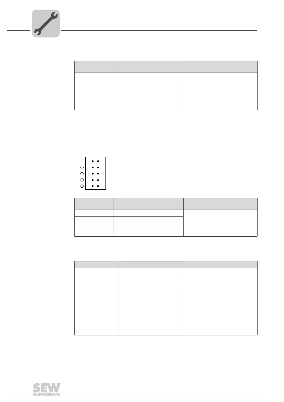
State of the LEDs
L6, L7, L8, L9
Diagnostics Troubleshooting
Off No voltage present.
-
Green Voltage at LED n.
Red Voltage at LED m.
Orange Voltage at LED n. and m.
X31
1
3
5
7
9
2
4
6
8
10
L6
L7
L8
L9
nm
Status of the LED L10 Diagnostics Troubleshooting
Green Voltage supply for the binary
inputs/outputs is OK.
-
Off Voltage supply for the binary
inputs/outputs is not applied.
1. Switch off the inverter in which the
MOVI-PLC
®
advanced DHE41B con-
troller is installed.
2. Check and correct the cabling of the
binary inputs/outputs according to the
electrical wiring diagram.
3. Check current consumption of the
connected actuators (max. current →
chapter 8).
4. Switch on the inverter in which the
MOVI-PLC
®
advanced DHE41B con-
troller is installed.
Orange Voltage supply for the binary
inputs/outputs is applied. However,
one of the following faults has
occurred:
• Overload on one or several
binary inputs/outputs
• Overtemperature of the output
driver
• Short circuit in at least one of
the binary inputs/outputs