UX-B700U
FO-B1600U
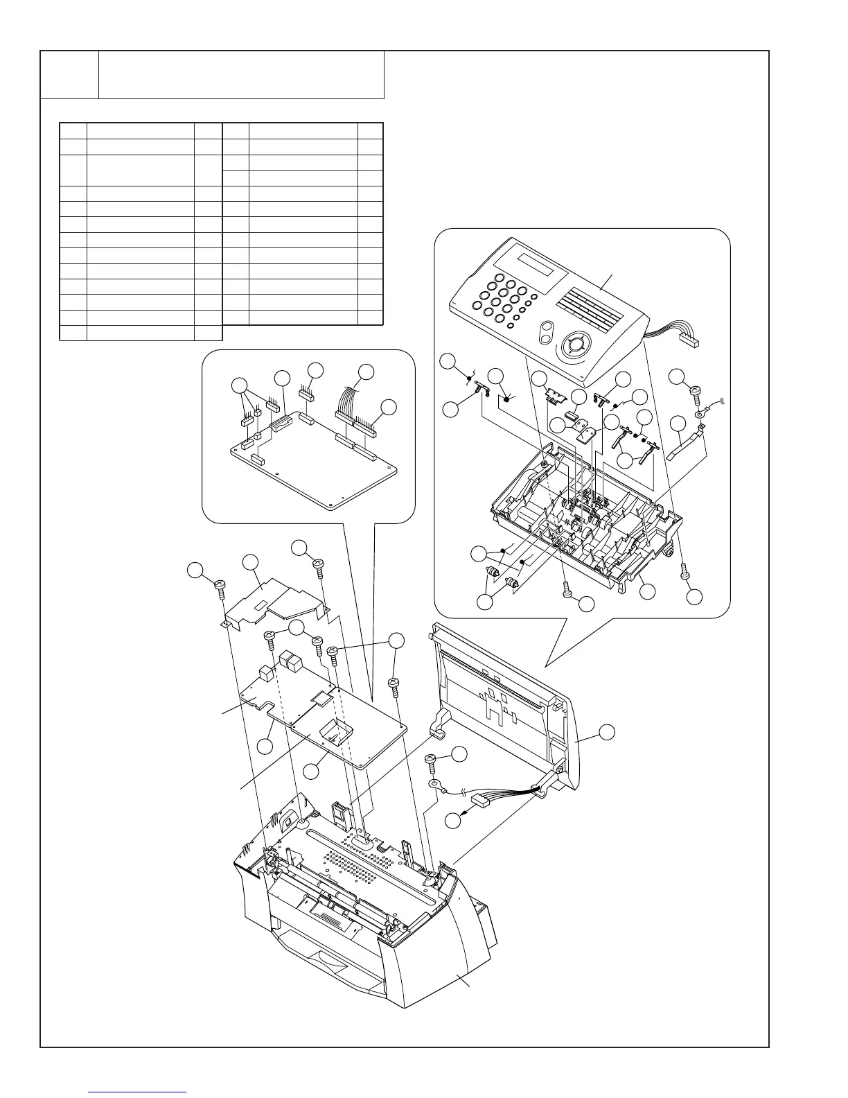
Operation panel unit, Control PWB unit,
TEL/LIU PWB unit
3
Fig. 3
3 – 8
NOTE: For disassembly of the inside of the
unit, refer to the exploded view in the
parts guide.
Control
PWB unit
12
A
21
A
22
21
21
14
13
18
19
18
23
24
2
3
3
3
9
8
15
13
16
17
20
20
7
6
Operation Panel
unit with PWB
1
Main unit
TEL/LIU
PWB unit
Control
PWB unit
4
10
11
5
Parts list (Fig. 3)
No. Part name Q’ty No. Part name Q’ty
1 Screw (3×10) 1
2 Operation panel unit/
Document guide upper 1
3 Screw (3×10) 3
4 Document guide upper 1
5 Earth sheet 2 1
6 Pinch pressure spring 2
7 Pinch roller 2
8 Separate spring 1
9 Separate plate 1
10 Separate cushion 1
11 Separate sheet 1
12 Separate rubber 1
13 Sub feed spring 2
14 Sub feed plate, left 1
15 Sub feed plate, right 1
16 Paper feed spring 1
17 Paper feed plate 2
18 Screw (3×10) 2
19 LIU upper plate 1
20 Screw (3×6) 4
21 Cable 5
22 Connector 1
23 Control PWB unit 1
24 TEL/LIU PWB unit 1