98
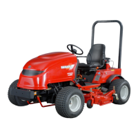
3. The identity mark fixed gear ①, when removed is
installed position A.
4. The shims ①, are installed between thrust washer ②,
and bearing ③, on the drive pinion ④.
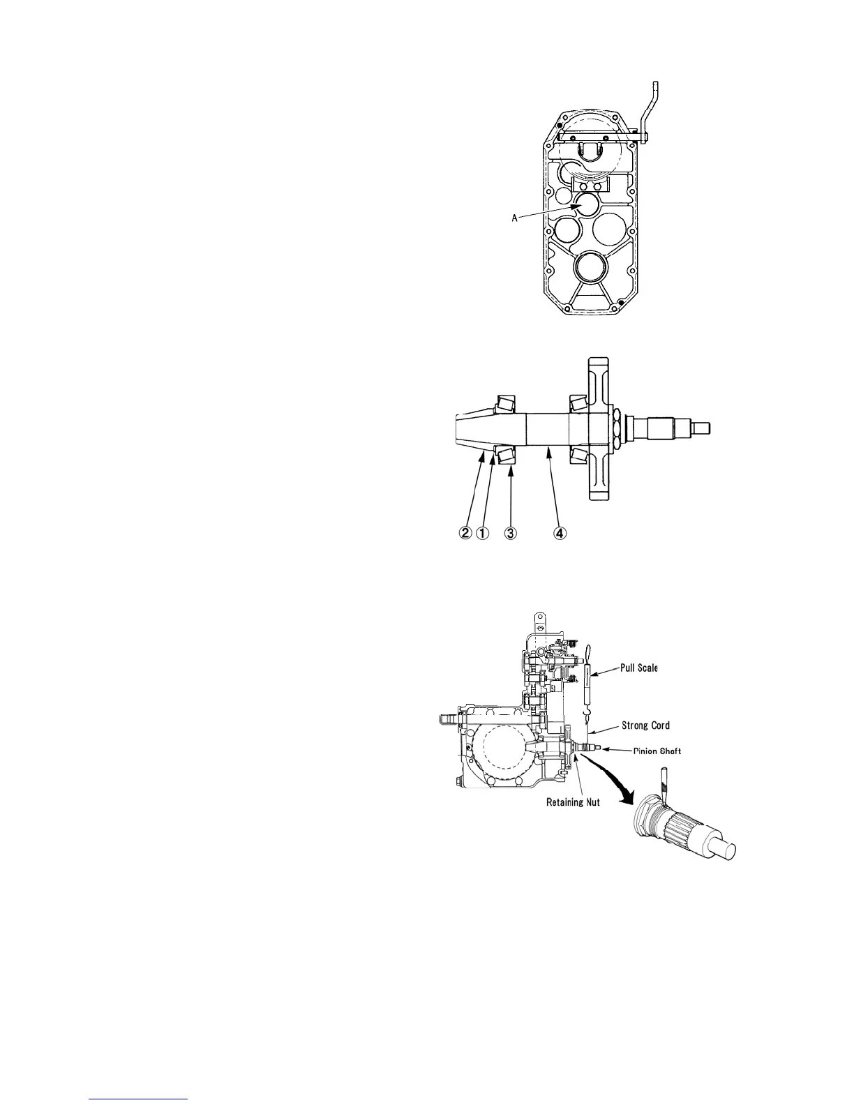
5. Adjust the pinion bearing pre-load using a strong cord
wrapped around the pinion shaft spline and a pull
scale. Tighten the pinion nut to obtain the specified
pounds of constant pull to rotate the pinion assembly.
Pinion Bearing Pre-Load Constant Pull 196 N {20
kgf}
NOTE: Turn drive pinion several times by hand
before performing pull scale test.
6. Bend the lock nut flange by the chisel at the ditch of
the pinion shaft after adjust the pre-load.
339X
340X
341X
 Loading...