22
Installation
Class 0 PoEuplink Class 0 PoEuplink Class 0 PoEuplink Class 0 PoEuplink
7
8
6
5
1
2
3
4
7
8
6
5
1
2
3
4
7
8
6
5
1
2
3
4
7
8
6
5
1
2
3
4
7
8
6
5
1
2
3
4
7
8
6
5
1
2
3
4
7
8
6
5
1
2
3
4
7
8
6
5
1
2
3
4
7
8
6
5
1
2
3
4
7
8
6
5
1
2
3
4
lockout
power
ethernet
network audio
push to solo | hold to mute
-9
-18
-24
-36
-48
-60
0
-9
-12
-18
-24
0
aux
mic
adjust
line
sig/clip
mute
INPUT
A
sig/clip
mute
OUTPUT
HEADPHONE
Audio Network Interface
MICROFLEX WIRELESS
B
1
2
3
4
5
6
7
8
line
aux
lockout
power
ethernet
network audio
push to solo | hold to mute
-9
-18
-24
-36
-48
-60
0
-9
-12
-18
-24
0
aux
mic
adjust
line
sig/clip
mute
INPUT
A
sig/clip
mute
OUTPUT
HEADPHONE
Audio Network Interface
MICROFLEX WIRELESS
B
1
2
3
4
5
6
7
8
line
aux
lockout
power
ethernet
network audio
push to solo | hold to mute
-9
-18
-24
-36
-48
-60
0
-9
-12
-18
-24
0
aux
mic
adjust
line
sig/clip
mute
INPUT
A
sig/clip
mute
OUTPUT
HEADPHONE
Audio Network Interface
MICROFLEX WIRELESS
B
1
2
3
4
5
6
7
8
line
aux
lockout
power
ethernet
network audio
push to solo | hold to mute
-9
-18
-24
-36
-48
-60
0
-9
-12
-18
-24
0
aux
mic
adjust
line
sig/clip
mute
INPUT
A
sig/clip
mute
OUTPUT
HEADPHONE
Audio Network Interface
MICROFLEX WIRELESS
B
1
2
3
4
5
6
7
8
line
aux
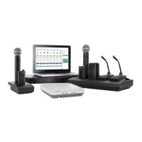
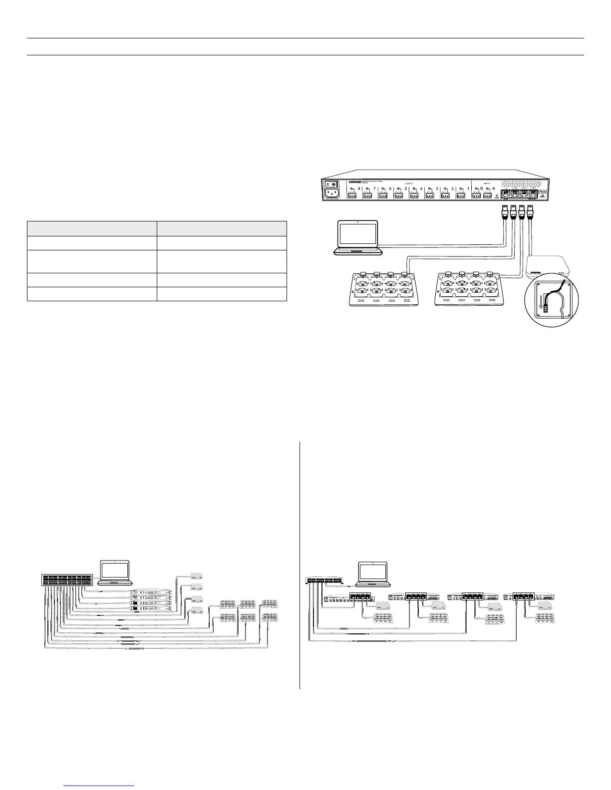
Connect the Components
MXW components are connected using Ethernet cables and a switch. For a small system with a single access point, the MXW Audio Network Interface
functions as the switch. For systems with more than one access point, an additional gigabit switch is required for connecting all the components together.
Requirements:
• Use shielded Cat 5e (or higher) Ethernet cables. Limit cable runs to ≤100 m between devices.
• Use Gigabit networking equipment between network audio devices (required for systems with >1 access point).
• Ensure MXW components are on the same firmware version.
• Ensure MXW components and the PC are on the same network and set to the same subnet.
Single Group System (1 Access Point)
When the system is limited to a single group (up to eight channels), use
the MXW Audio Network Interface four-port switch for connecting MXW
components. Connect the computer, access point and up to two chargers
to the MXW interface according to the table and diagram:
Audio Network Interface Port To Component
① Port 1 (PoE) Access Point Transceiver (APT)
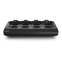
② Port 2
Networked Charging Station
(NCS)
③ Port 3 (Optional) Additional NCS
④ Port 4* Computer
*When Port 4 is set to Uplink mode, Shure Discovery Application
support is restricted.
Multiple Group System (>1 Access Point)
When an installation requires more than eight channels, additional MXW components can be connected to expand the system. Depending on the RF spectrum
availability, a system can contain up to 40 channels in North America and 80 channels in Europe. See the Wireless Management section to ensure reliable RF
stability.
For systems with more than one APT, a gigabit router is required to connect all components to the same network. The following are several topologies for
multiple group systems.
②
④
①
7
8
6
5
1
2
3
4
7
8
6
5
1
2
3
4
③
Large Single-Room Installation
1. Power on the DHCP-enabled router.
2. Connect the router to a computer.
3. Connect each APT to a Power over Ethernet (PoE)-enabled port on the
router. Use a PoE inserter if the router does not provide it.
4. Connect each ANI to the router.
5. Connect chargers to the ANI ports, or to the router.
Star Configuration (recommended)
Local System Star Setup
To minimize cabling, MXW components can use the Audio Network
Interface as a local switch that connects to a shared network.
1. Power on the DHCP-enabled router.
2. Connect the router to a computer.
3. Connect the router to Port 2, 3, or 4 on the Audio Network Interface
4. Connect the Access Point Transceiver to the Port 1 of the Audio
Network Interface.
5. Connect the Network Charging Station(s) to an open port(s) on the
Audio Network Interface.
6. Repeat steps 2 - 4 for additional equipment.
Local System Star to Network (minimal cabling)