7
System Overview
Technology Overview of the Audio Path
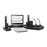
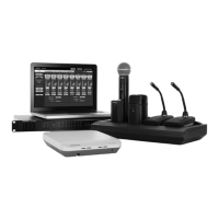
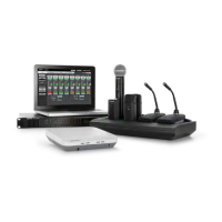
The MXW System combines Shure's legendary audio quality with advanced digital networking technology. The following is an overview of the audio path:
Basic System Concepts
Forming Groups and Linking Microphones
Once all the MXW components are connected to the network, they can be
associated into Groups from the Configuration tab of the control software.
Each Access Point can form an association Group with one or two
chargers (for Linking microphones) and one or two audio output devices
(for routing audio to analog outputs). The microphones can then be placed
in the charger and Linked to these access point channels.
Each Group is managed by a single access point. Microphones are Linked
to channels in the access point, not to the charger that was used to Link
them. This relationship persists until the microphones are re-Linked or the
access point is reset.
Configurations: Managing Multiple Groups
Configurations allow multiple Groups to share the same preferences and
global controls. When an additional Group is added to a Configuration
page, a relationship is established across all devices in the configuration.
The new Group will take on the settings of that configuration.
For specialized applications such as multiple room setup, several
configurations can be created to independently control component Groups.
7
8
6
5
1
2
3
4
7
8
6
5
1
2
3
4
Key
lockout
power
ethernet
network audio
push to solo | hold to mute
-9
-18
-24
-36
-48
-60
0
-9
-12
-18
-24
0
aux
mic
adjust
line
sig/clip
mute
INPUT
A
sig/clip
mute
OUTPUT
HEADPHONE
Audio Network Interface
B
1
2
3
4
5
6
7
8
line
aux
MICROFLEX WIRELESS
lockout
power
ethernet
network audio
push to solo | hold to mute
-9
-18
-24
-36
-48
-60
0
-9
-12
-18
-24
0
aux
mic
adjust
line
sig/clip
mute
INPUT
A
sig/clip
mute
OUTPUT
HEADPHONE
Audio Network Interface
B
1
2
3
4
5
6
7
8
line
aux
MICROFLEX WIRELESS
lockout
power
ethernet
network audio
push to solo | hold to mute
-9
-18
-24
-36
-48
-60
0
-9
-12
-18
-24
0
aux
mic
adjust
line
sig/clip
mute
INPUT
A
sig/clip
mute
OUTPUT
HEADPHONE
Audio Network Interface
B
1
2
3
4
5
6
7
8
line
aux
MICROFLEX WIRELESS
Group 1
Group 2
Group 3
2
2
3
1
1
1
Digital audio and
control network
Analog audio output
Channel link data
3
Wireless Audio
The MXW transmitter converts speech into a digital signal that is
transmitted wirelessly to the access point.
• Intelligent, automatic wireless audio management using the Digital
Enhanced Cordless Telecommunications (DECT) framework
• Custom RF design enables higher audio quality and lower latency than
most DECT systems
• Up to 40 Microflex Wireless channels can operate in the unlicensed
1920–1930 MHz frequency bands. In Europe, up to 80 channels can
operate simultaneously in the 1880–1900 MHz frequency range.
Digital Audio Network
The access point receives wireless audio from the microphones and
distributes it to the audio network interface.
• Low latency, tight clock synchronization, and high Quality-of-Service
(QoS) provide reliable audio transport.
• Digital audio is carried over Ethernet cables and standard IP equipment.
• Audio coexists safely on the same network as IT and control data, or
can be configured to use a dedicated network.
Analog Audio
The audio network interface converts network audio for each channel into
analog outputs.
• Sends analog audio to a mixer, Digital Signal Processor (DSP), or
teleconferencing device.