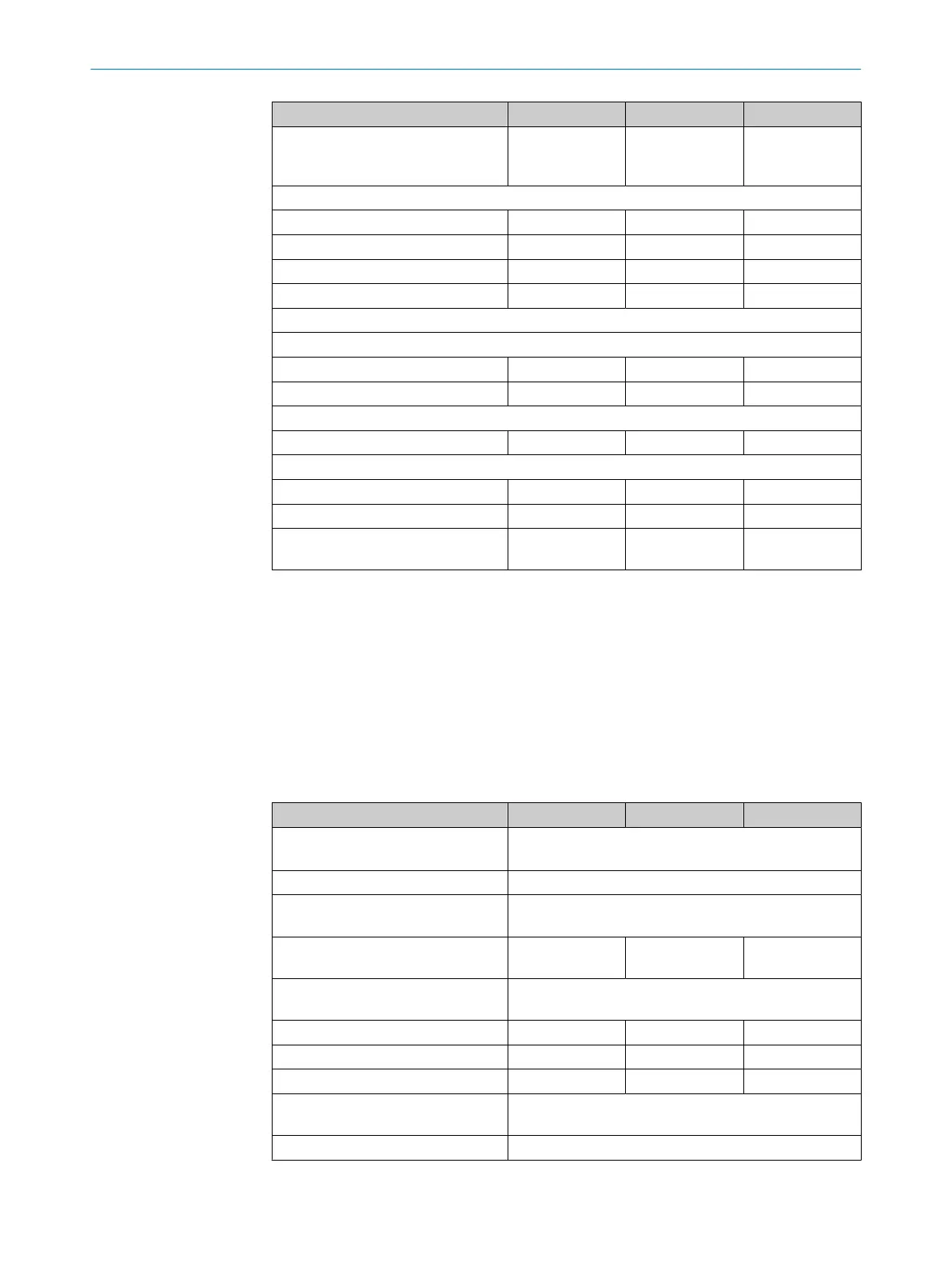
Minimum Typical Maximum
Discrepancy time (time offset
be
tween switching of OSSD2 and
OSSD1)
1 ms
Inputs
Input voltage HIGH (active)
2)
11 V 24 V 30 V
Input current HIGH 6 mA 10 mA 20 mA
Input voltage LOW (deactivated)
2)
0 V 5 V
Input current LOW -2.5 mA 0 mA 0.5 mA
External device monitoring input (EDM)
Connected contactors
Permissible dropout time 300 ms
Permissible pull in time 300 ms
Reset pushbutton input (RES)
Control switch actuation time 50 ms
Permissible cable resistance
5)
Supply cable
6)
1 Ω
Cable between OSSD and load 2.5 Ω
All additional wires at the system
c
onnection and extension connection
2.5 Ω
1)
Applies to the voltage range between -30 V and +30 V.
2)
According to IEC 61131-2.
3)
The specified values are the switching voltage supplied by the safety light curtain. If higher voltages are
im
planted externally, the maximum value of 2.0 V can be exceeded.
4)
When active, the outputs are tested cyclically (brief LOW). When selecting the downstream controllers,
make sure that the test pulses do not result in deactivation when using the above parameters.
5)
Limit the individual conductor resistance to the specified values to ensure that the light curtain func‐
tions correctly, particularly that a cross-circuit between the outputs is safely detected. (Also observe
IEC 60204-1.)
The specified values apply to the total resistance of each wire including contact and connector resistan‐
ces.
6)
The supply cable must not be used to connect other loads with the exception of the senders.
Table 31: Operating data
Minimum Typical Maximum
System connection 5-pin M12 male connector
8-pin M12 male connec
tor
Extension connection Optional, female connector, M12, 5-pin
Length of cable for connecting
c
ables
"Length of cable", page 83
Lengths of cable for other cables on
the extension connection
10 m
Cable material of the system of
e
xtension connection
PUR
Ambient operating temperature
1)
2)
3)
-30 °C +55 °C
Air humidity (non-condensing) 15% 95%
Storage temperature -30 °C +70 °C
Housing cross-section 31 mm × 34 mm, plus bracket, see "Dimensional dr
aw‐
ings", page 84
Vibration resistance
4)
5 g, 10 Hz … 55 Hz (IEC 60068-2-6)
TECHNICAL DATA 13
8027140/2021-11-04 | SICK O P E R A T I N G I N S T R U C T I O N S | deTec4
81
Subject to change without notice
 Loading...


