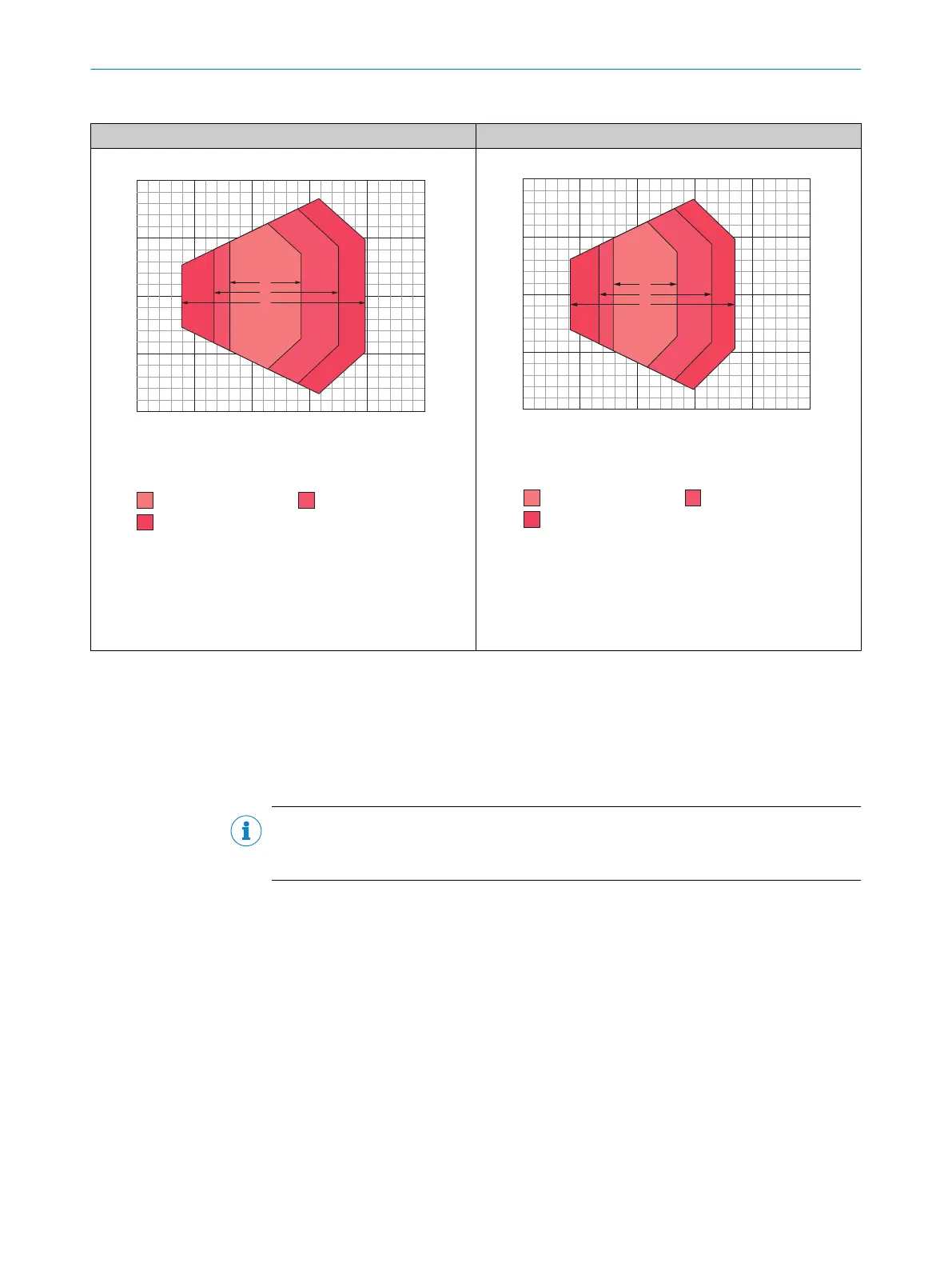
Table 5: Reading fields of CLV631 with oscillating mirror and side reading window
CLV631 in standard housing CLV631 in IP69K protective housing
500
(19.69)
300
(11.81)
400
(15.75)
200
(7.87)
100
(3.94)
0
Reading distance in mm (inch) 2
Resolution 3
a: 0.25 mm (9.8 mil)
c: 0.50 mm (19.7 mil)
b: 0.35 mm (13.8 mil)
–100
(–3.94)
–200
(–7.87)
100
(3.94)
200
(7.87)
0
Reading field height in mm (inch) 1
a
b
c
Figure 10: Reading field diagram of CLV631-6120, oscillating
mirror and side reading window
1
Reading field height in mm (inch)
2
Reading distance in mm (inch)
3
Resolution
a
b
c
–100
(–3.94)
–200
(–7.87)
100
(3.94)
200
(7.87)
0
Reading field height in mm (inch) 1
500
(19.69)
300
(11.81)
400
(15.75)
200
(7.87)
100
(3.94)
0
Reading distance in mm (inch) 2
Resolution 3
a: 0.25 mm (9.8 mil)
c: 0.50 mm (19.7 mil)
b: 0.35 mm (13.8 mil)
Figure 11: Reading field diagram of CLV631-6831S01, oscil‐
lating mirror and side reading window
1
Reading field height in mm (inch)
2
Reading distance in mm (inch)
3
Resolution
Display of reading field diagrams in SOPAS ET
The SOPAS ET configuration software displays the reading field diagrams of the bar
code scanners in standard housing (reading window made of glass). The diagrams
therefore do not provide a true representation of the restricted and displaced reading
areas of the bar code scanners in IP69K protective housing (reading window made of
plastic).
NOTE
As a simplified rule: the depth of field is reduced by approx. 10% for devices with a plas‐
tic reading window.
PRODUCT DESCRIPTION 3
8021479/0000/2018-03-12 | SICK T E C H N I C A L I N F O R M A T I O N | CLV62x, CLV63x and CLV64x with IP69K Protective Housing
17
Subject to change without notice

 Loading...


